
|
|
1.IntroductionLarge cryogenic space telescopes may provide a means of answering several compelling astrophysics questions, but the required increase in the primary mirror diameter presents numerous technical challenges. Proposed investigations of early star formation, planetary system evolution, and the presence of large organic molecules in interstellar disks, for example, require a 10- to 16-m class far-IR to submillimeter space telescope; in this wavelength range, atmospheric extinction precludes ground-based measurements, and existing space telescopes suffer from source confusion.1–4 It is also expected that high-resolution far-IR observations will lead to new discoveries, possibly concerning the emergence of cosmic structure.4,5 However, for an observatory to obtain an angular resolution in the far-IR that is comparable to Hubble’s resolution in the visible, its diameter must be on the order of 1 km.5 By comparison, Herschel, the largest space telescope to operate in the far-IR to submillimeter range, has a primary diameter of 3.5 m.6 As the primary mirror diameter of future cryogenic observatories increases, maintaining a stable wavefront becomes increasingly challenging since the first natural frequency decreases as the diameter squared, the material damping is negligible, and other common damping methods break down at low temperatures.7–11 Although large stiff precision structures are considered an enabling technology for large cryogenic mirrors,12 an alternative approach to increasing mirror stability is to use an edgewise-connected architecture. In this approach, mechanisms analogous to damped springs are placed along the edges of the primary mirror segments. The stiffness and damping contributions from the mechanisms reduce the requirements for the supporting structure, and if the mechanisms are sufficiently stiff, the segmented mirror performs comparably to a monolith even if the mechanisms are the only structural connections to the segments.13 While the mechanisms can be a collection of damped springs or any other device with similar behavior, flux-pinning mechanisms are uniquely suited for cryogenic mirrors. Unlike mechanical devices, which can have problems with lubrication, coefficient of thermal expansion (CTE) matching, and thermal snap, flux-pinning mechanisms operate best at cryogenic temperatures. These passively stable, noncontacting mechanisms consist of a collection of magnets and type II superconductors and require only low temperatures; no power is needed other than the minimal amount, if any, necessary for cooling. Like a flexure, a flux-pinning mechanism preferentially allows motion in specific degrees of freedom, which depend on the mechanism design, as described in Sec. 2. Motion in the nonpreferred degrees of freedom is resisted by a force analogous to a damped spring force, and the stiffness and damping can be adjusted independently. These mechanism properties depend on the choice of magnets, the separation between the magnets and superconductors, and the presence of nonmagnetic conductive materials, such as aluminum. As an example, we consider simple mechanisms consisting of an inexpensive magnet and a single superconductor separated by distances on the order of 1 mm (Secs. 3 and 4). These mechanisms can be trained to follow a particular displacement pattern when loaded, and they provide increasing resistance the closer the magnet and superconductor—or mirror segments attached to each—come to colliding. Typical stiffness and damping values are on the order of and , respectively (Sec. 3). As shown in Sec. 4, mechanisms with these values provide modest improvements to the performance of an edgewise-connected mirror. Greater gains can be achieved by using stronger magnets or smaller separations, or by placing nonmagnetic conductive materials near the mechanism. 2.Flux-Pinning MechanismsFlux pinning, a physical interaction between a magnet and a type II superconductor, is analogous to a noncontacting damped spring force. This force is due to the presence of impurities that allow the magnetic field to penetrate into the superconductor material. As the superconductor cools below its critical temperature [approximately 90 K for yttrium barium copper oxide (YBCO)14], the magnetic field lines are “frozen” in place; motions that change the magnetic field distribution inside the superconductor induce supercurrents that oppose the change. As a result, the relative orientation and position of the magnet and superconductor are passively stabilized in every direction that has a magnetic field gradient. A useful conceptual model is the frozen-image model, which explains the forces between a magnet and a type II superconductor by replacing the superconductor with two image magnets.15 The first image magnet, called the mobile image, is a reflection of the permanent magnet across the superconductor surface (Fig. 1). This image moves as the permanent magnet moves, and since the two magnets have opposite moments, the interaction between them is repulsive. The second image magnet, called the frozen image, is stationary. This image is almost a perfect reflection of the permanent magnet at the time the superconductor cooled below its critical temperature; the orientation and position of the frozen image are reflections of the orientation and position of the permanent magnet at this time, but the magnetic moment is in the same direction as that of the permanent magnet. The force on the permanent magnet is the sum of the forces due to each image magnet. As a result, the permanent magnet is in equilibrium when it is in its initial orientation and position since the forces from the images cancel. As the magnet moves closer to the superconductor, the force from the mobile image dominates, and the magnet is repelled. Similarly, as the magnet moves further from the superconductor, the force from the frozen image dominates, and the magnet is attracted. Fig. 1Image model for flux pinning. In this model, flux pinning is described as the interaction between the permanent magnet and two image magnets that form as the superconductor cools below its critical temperature (a, b). The mobile image is a mirror image of the permanent magnet, and it moves as the permanent magnet moves (c). The frozen image is almost a mirror image of the permanent magnet at the moment the superconductor cools below its critical temperature; the orientation and position are mirror images, but the dipole vector is the same. The frozen image does not move. The force on the permanent magnet is the sum of the forces due to the image magnets.  For small motions, the force between the magnet and superconductor is analogous to a damped spring force, with the stiffness and damping determined by a variety of factors including the choice of magnet and superconductor, the separation during cooling, and the presence of conductive materials.16–18 For a cylindrical magnet levitated over a cylindrical superconductor, the stiffness for motions perpendicular to the magnet-superconductor interface has been determined empirically to be approximately twice the stiffness for motions parallel to the interface,19,20 and the stiffness increases nearly exponentially as the cooling separation decreases.16 Stiffer interfaces result from using stronger magnets, stronger superconductors, and smaller separations. Additionally, the amount of damping can be increased independently by placing nonmagnetic conductive materials, such as aluminum, near the interface. The inherent damping arises from hysteretic losses,21,22 and placing nonmagnetic conductive material nearby increases the total damping by providing a source of eddy current damping. Previous experiments have demonstrated that placing aluminum near the magnet and superconductor can increase the damping substantially, altering the response from imperceptibly damped to strongly overdamped.16 A flux-pinning mechanism is a configuration of magnets and superconductors that, like a flexure, preferentially allows motion in specific degrees of freedom. Since the mechanism stiffness depends on the magnet–superconductor cooling separation, these mechanisms fall into two broad categories: low-stiffness mechanisms that prioritize larger separations, and low-separation mechanisms that prioritize higher stiffness. Prior research into flux-pinning mechanisms has concentrated on designing mechanisms that serve as joints between spacecraft modules.16,23,24 While these mechanisms belong in the first category since large separations are desired, similar techniques can be applied to designing optomechanical interfaces, which typically require high stiffnesses in order to control motion to a fraction of a wavelength.25–28 Since flux pinning resists changes to the magnetic field distribution inside the superconductor, one design approach is to shape the magnetic field so that it is constant in directions where motion is desirable. For example, to allow only translation along a line, like a parallel-blade flexure, one mechanism design consists of a cubical superconductor pinned between two long cylindrical magnets [Fig. 2(a)].Fn1 Since a line between and parallel to the magnets is the only direction without a magnetic field gradient, it is the only direction in which the superconductor can move freely; the geometry of the superconductor restricts rotation about this line. Similarly, to allow only rotation about an axis, like a cross-blade flexure, the flux-pinning mechanism consists of a small cylindrical magnet pinned above a superconducting disk, as shown in Fig. 2(b). Since the line connecting the magnet and superconductor is an axis of symmetry for the magnetic field, rotations about this axis are unconstrained. Motions in any other direction, however, are opposed by a restoring force since there is a magnetic field gradient. Fig. 2Flux-pinning mechanisms and the corresponding flexures. Like a flexure, a flux-pinning mechanism preferentially allows motion in specific degrees of freedom. These degrees of freedom depend on the mechanism design, and there are two basic design approaches: shaping the magnetic field so that there is no change in the degrees of freedom in which motion is desired (a, b), and combining field shaping with mechanical constraints (c).  An alternative approach to flux-pinning mechanism design is to combine field shaping with mechanical constraints. As an example, a flux-pinning mechanism analogous to a wire flexure consists of a cylindrical superconductor pinned to a spherical magnet mounted inside an inverted cone [Fig. 2(c)]. This mechanism allows motion in five degrees of freedom. As before, the line connecting the magnet and superconductor is an axis of symmetry for the magnetic field, so the superconductor is free to rotate about this axis without disturbing the magnet. However, a springlike restoring force opposes any motions that change the relative orientation and position of the magnet, such as motion along the line connecting the two. As a result, rotating the superconductor about the cone will cause the magnet to rotate correspondingly since it is free to move within the cone; radial translation is the only motion the mechanism resists. For the edgewise-connected mirror analysis that follows, we have selected the mechanism described in Fig. 2(b). This mechanism consists of a 56-mm single-domain melt-textured YBCO disk14 paired with a neodymium disk magnet, and the cooling separation varies from 0.5 to 2 mm. To represent this mechanism as a collection of collocated damped springs, it is assumed that all of the important dynamics can be captured by considering only the relative translations between the magnet and superconductor. While this mechanism does resist bending to some extent, it is assumed that the resistance from a single mechanism is negligible. Instead, bending stiffness is added by using pairs of mechanisms, as shown in Fig. 3, separated by a distance . Fig. 3The mechanism model. As an example, we consider the case of an edgewise-connected mirror using the flux-pinning mechanisms shown in Fig. 2(b). While these mechanisms resist bending to some extent, it is assumed that the resistance from a single mechanism is negligible; bending stiffness is added by using pairs of mechanisms, as circled on the segment in (a). In the model, each pair of mechanisms is represented by a set of four collocated single-degree-of-freedom damped springs (b), capturing the resistance to bending and translation. [Note that in (b), each set of four collocated springs is drawn as a single spring-damper pair]. 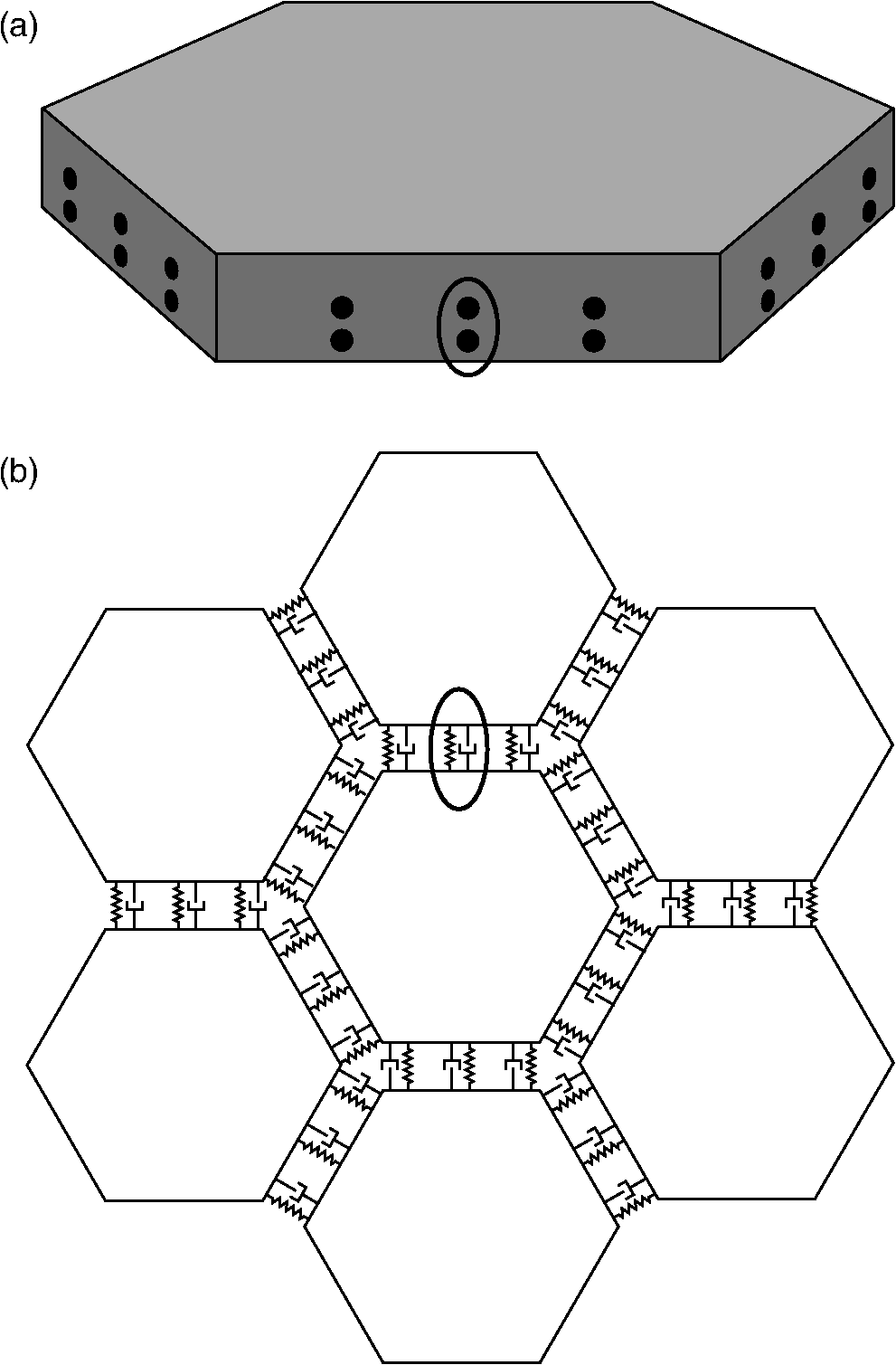 In this model, there are two rows of mechanisms along each segment edge, and each pair of mechanisms is represented by a set of four collocated single-degree-of-freedom damped springs. One of these damped springs corresponds to translation perpendicular to the superconductor surface, with stiffness , and two of the springs correspond to translation parallel to the superconductor surface, with stiffness . The remaining spring corresponds to bending, with stiffness . Since flux pinning is approximately twice as stiff for motion perpendicular to the magnet-superconductor interface as it is for motion parallel, we assume that is twice , and to account for the two rows of mechanisms, and are also twice the values for a single mechanism. Finally, for simplicity, the damping is assumed to be isotropic. 3.Mechanism CharacterizationThe performance of an edgewise-connected mirror depends on the mechanism stiffness and damping.13 For a flux-pinning mechanism, these properties are affected by design choices including the cooling separation, the magnet strength, and the presence of conductive materials. To investigate the achievable stiffness and damping for mechanisms with cooling separations on the order of millimeters, rather than centimeters, we conducted a series of static and dynamic measurements for various mechanisms of the type shown in Fig. 2(b). The static measurements provide insight into the basic mechanism behavior (Sec. 3.2), while the dynamic measurements illustrate how the stiffness and damping depend on the mechanism parameters (Sec. 3.3). These static and dynamic measurements required constructing a specialized apparatus to address challenges posed by the need for cryogenic temperatures and the requirement for materials that would not interact with the mechanism, as described in Sec. 3.1. 3.1.Measurement ApparatusThe stiffness and damping measurements present a number of practical challenges since flux-pinning mechanisms require cryogenic temperatures and interact with magnetic or conductive materials. For high-temperature superconductors such as YBCO,14 the critical temperature is high enough that the mechanisms can be cooled in liquid nitrogen rather than using a cryogenic chamber. If this technique is used, the measurement apparatus must be able to withstand the repeated thermal shocks and large temperature gradients associated with rapidly cooling the mechanism. Low thermal conductivity and a low CTE are also desirable to minimize the frequency of replenishing the liquid nitrogen and the effects of temperature fluctuations. The apparatus must also be sufficiently stiff that the experiments measure the stiffness of the mechanism, not the apparatus. Finally, the apparatus cannot be constructed from magnetic or conductive materials, which would interact with the mechanism and interfere with the measurements.Fn2 To address these challenges, we fabricated a specialized measurement apparatus using Zerodur, a low-expansion ceramic.29 This apparatus has two configurations: a static configuration for measuring the perpendicular stiffness and a dynamic configuration for measuring the parallel stiffness and damping. In the static configuration, a lever arm measures displacements perpendicular to the magnet-superconductor interface as the mechanism is loaded and unloaded incrementally with known weights [Fig. 4(a)]. In the dynamic configuration, a cantilever suspends the magnet over the superconductor, with a parallel-blade flexure restricting the motion to a line parallel to the superconductor surface (Fig. 5). In both configurations, the superconductor rests on a Zerodur platform insulated by a Styrofoam box that contains the liquid nitrogen; areas outside this box are at room temperature except as cooled by stray nitrogen vapors or thermal conduction. For stability, the platform is supported by three Zerodur legs that pass through the Styrofoam to rest on a granite table. To allow for switching between configurations, the lever arm and cantilever are both removable, aside from their support posts, which are fixed to the platform. The lever arm, cantilever, and support posts are all constructed of Zerodur as well. Fig. 4The static measurements (schematic). To determine the perpendicular stiffness, changes in the magnet-superconductor separation are measured as the mechanism is loaded with a sequence of known weights. These weights are placed on a lever arm that rotates as the magnet-superconductor separation changes, and the changes are measured by reflecting a laser off a mirror attached to the lever arm and tracking the location of the reflected beam spot (a). The displacement due to the applied weight corresponds to a rotation angle of , which can be determined from the location of the reflected beam spot by considering the experiment geometry (b). In the figure, the various show how the mirror normal is affected by thermal effects, various misalignments, and any applied weight. As an example, cooling the apparatus from room temperature to cryogenic temperatures causes the mirror normal to change from to since contraction of the mechanism rotates the lever arm by . The final mirror normal, which accounts for the misalignments, thermal effects, and applied weight, is denoted by . (Angles in the figure have been exaggerated for clarity).  Fig. 5The dynamic measurements (schematic). The parallel stiffness and damping are determined by measuring the impulse response. For these measurements, a cantilever suspends the magnet over the superconductor, with a parallel-blade flexure restricting the motion to a line parallel to the superconductor surface. 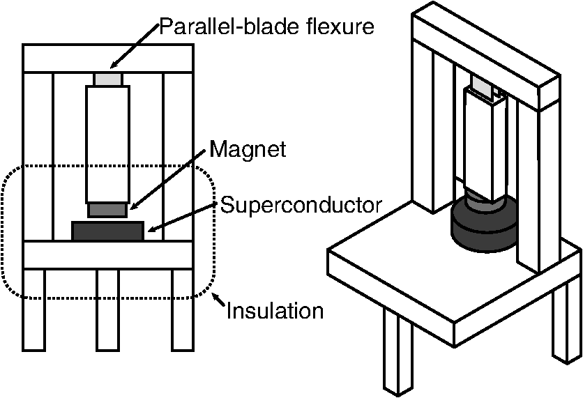 3.2.Static Measurements (Perpendicular Stiffness)To determine the perpendicular stiffness and investigate the mechanism behavior, we measured changes in the magnet-superconductor separation as the flux-pinning mechanism was loaded with a sequence of known weights and incrementally unloaded. In these static experiments, the superconductor was constrained so that changes in the magnet-superconductor separation corresponded to displacements of the magnet. These displacements, , were measured by reflecting a laser off a mirror mounted to a lever arm that rotated as the separation changed, and tracking the location of the reflected beam spot on a target a distance away (Fig. 4). The raw measurements, then, consisted of a set of positions for the reflected beam spot. We determined these positions, , by inking each location directly on the target and, after testing, using a drafting machine to meticulously measure the distance between each location and a reference line. Processing this raw data requires relating changes in to , which can be accomplished by considering the experiment geometry and the changes that occur as the mechanism and apparatus transition from room temperature to cryogenic temperatures and as the spacer that constrains the magnet–superconductor separation during cooling is removed. At room temperature, the location of the reflected beam spot is determined by the deviation of the mirror normal from 45 deg, , the laser misalignment, , and the initial tilt of the lever arm, [Fig. 4(b)]. Since the pivot mirror rotates with the lever arm, the total tilt changes the height of the spot where the laser intersects the mirror, shifting the height of the reflected beam by . As liquid nitrogen is added, the apparatus expands/contracts on a global scale, changing the position of the reflected beam spot by . Similarly, contraction of the magnet, superconductor, and spacer alters the total height of the mechanism, causing the pivot arm to rotate by an additional amount . These two effects are distinguished by comparing changes in the location of the reflected pivot beam spot to changes in the location of a reflected spot from a laser aimed at a reference mirror attached to a stationary part of the apparatus. After the experiment reaches thermal equilibrium, the spacer between the magnet and the superconductor is removed, and the mechanism is loaded with a known weight. As the magnet-superconductor separation decreases in response to the weight, the lever arm rotates by an additional amount . At each stage of the experiment, the translation of the reflected pivot beam spot is related to the total lever arm rotation, , by where is the height of the reflected pivot beam spot relative to the height of the point where the beam intersects the mirror when the experiment is at room temperature.Fn3 Since is given by where and are points on the mirror surface and is the point where the beam hits the mirror initially,Fn4 Eq. (1) can be rewritten asThe various rotation angles are determined by iteratively solving Eq. (2) for and noting that To relate to the displacement caused by adding the weight, , we begin by noting that once the experiment reaches thermal equilibrium, the height of the lever arm pivot point relative to the bottom of the superconductor, , is a constant. Before the spacer is removed, is given by where is the distance from the pivot point to the end of the lever arm, is the length of the vertical section of the lever arm, is the thickness of the Zerodur disk at room temperature, is the change in due to cooling, is the distance from the bottom of the superconductor to the top of the magnet at room temperature, and is the change in due to cooling (Fig. 6). After the spacer is removed and weights are applied, is given by Equating these two expressions and solving for , we find that which for small angles reduces toFig. 6Relating to the magnet displacement. Since the height of the lever arm pivot point relative to the bottom of the superconductor is a constant, the amount of rotation caused by adding weight, , and the corresponding magnet displacement, , are related by for small angles.  For our experiments, the target was placed a distance away, while the distance from the pivot point to the end of the lever arm was . As a result, changes in the magnet-superconductor separation were magnified by approximately a factor of 280; a 0.5-mm change in the separation, for example, caused the reflected beam spot to move 140 mm on the target. All of the misalignment angles and were less than 1 deg (, , , and ), and since the magnet-superconductor separation was at most 2 mm, also did not exceed 1 deg. Consequently, the total rotation angle did not exceed 2.5 deg, justifying the small angle assumption. To investigate the mechanism behavior, the mechanism was loaded with a sequence of weights, gradually increasing to a maximum of , then unloaded in reverse order. After several repetitions, was incremented to a new value. As Fig. 7 shows, the resulting displacement pattern is affected by the heaviest weight that has ever been applied, . As increases, the pattern shifts toward larger displacements. (If is less than , the pattern does not shift back toward smaller displacements.) This effect appears to be an offset only, with no effect on the stiffness; when the offset between the average initial displacements for two sequences is subtracted, the data points for both sequences fall on the same curve. For practical purposes, this hysteretic behavior has two implications: the mechanisms can be trained to have a particular displacement pattern if the maximum load remains below some threshold, and the displacements will increase if this threshold is exceeded. Since the mechanisms are situated along the segment edges, the ability to specify the displacement pattern corresponds to an ability to specify the size of the gap between adjacent segments, which may prove beneficial in situations where the gap must remain above a minimum value. Fig. 7The importance of . As the mechanism is sequentially loaded or unloaded, the displacement pattern depends on the maximum weight that has ever been applied, , rather than the heaviest weight in the sequence, . Increasing shifts the pattern toward larger displacements without affecting the stiffness, and the pattern does not shift back toward smaller displacements if . As an example, the displacement data from a sample experiment is shown, with different symbols representing various weight sequences. For the initial sequence, one weight is applied and removed repeatedly, causing the displacement to oscillate between two values. For the second sequence, two weights are applied in order, then removed. Initially, the displacement pattern is the same as for the first sequence, but once the applied weight exceeds the previous value of , the displacements change, following a different pattern as the weights decrease. This new pattern is then followed (whether weights are added or removed) until a subsequent sequence increases .  The stiffness values can be estimated from the displacement pattern by approximating the derivative between adjacent data points. For two points and , the stiffness corresponding to the mean displacement is approximately As Fig. 8 shows, the stiffness is nonlinear, and the shape of the curve depends on both the cooling separation and the magnet displacement. Decreasing the cooling separation increases the stiffness, as expected, and also leads to smaller shifts as increases. For a fixed cooling separation, the stiffness varies by an order of magnitude as the magnet-superconductor separation diminishes, increasingly sharply as the separation approaches zero. This increase is to be expected; previous work suggests that the stiffness increases nearly exponentially as the magnet approaches the superconductor.30,31 This behavior may prove beneficial in an edgewise-connected mirror: the mechanisms provide increasing resistance the closer the two segments come to colliding.Fig. 8The perpendicular stiffness. As the magnet approaches the superconductor, the stiffness varies by an order of magnitude, increasing sharply as the magnet-superconductor separation vanishes. As a result, the flux-pinning mechanism provides increasing resistance the closer two segments in an edgewise-connected mirror come to colliding. Decreasing the cooling separation leads to stiffer mechanisms.  3.3.Dynamic Measurements (Parallel Stiffness and Damping)To determine the parallel stiffness and damping and study their dependence on the mechanism implementation, we measured the impulse response for mechanisms with various magnets and cooling separations of 0.5–2 mm. Since flux pinning is affected by the shape and strength of the magnetic field present during cooling, magnets of different diameter and thickness were tested. In addition to conventional magnets, we also tested a Swirl magnet, a neodymium magnet imprinted with a magnetic field pattern that preferentially allows rotational motion.32–34 This pattern was selected in order to investigate whether the rapidly changing magnetic field and its resistance to translation correspond to an increase in . For each mechanism, the stiffness and damping were extracted from the impulse response using eigensystem realization analysis,35 and the results of multiple trials were averaged. As shown in Figs. 9 and 10, and generally increase as the cooling separation decreases or the magnet strength increases. These trends are to be expected since both stronger magnets and smaller cooling separations increase the magnetic flux penetrating into the superconductor during cooling; previous measurements have suggested that the stiffness increases nearly exponentially as the cooling separation decreases.16,36 For the mechanisms tested, the effects of varying the cooling separation are particularly noteworthy. As the cooling separation decreased from 2 to 0.5 mm, the stiffness increased by a factor of 2–10, with typical values on the order of , and the damping increased by up to an order of magnitude, with typical values on the order of 1–. By comparison, previous measurements using comparable mechanisms with a cooling separation of 5 cm reported stiffnesses on the order of and no discernible damping.16 Fig. 9The parallel stiffness for various mechanisms. In general, stronger magnets and smaller cooling separations lead to stiffer mechanisms. With cooling separations on the order of 1 mm, the mechanisms tested typically have stiffnesses on the order of . [Note that in some cases, the error bars are smaller than the symbols.] By comparison, previous measurements for similar mechanisms with cooling separations on the order of 5 cm reported stiffnesses on the order of .16  Fig. 10The damping for various mechanisms. With cooling separations on the order of , the mechanisms tested typically have damping values on the order of 1–. [Note that in some cases, the error bars are smaller than the symbols.] Smaller cooling separations and stronger magnets generally correspond to higher damping. By comparison, previous measurements with similar mechanisms and cooling separations on the order of 5 cm reported no discernible damping.16  While additional testing is needed to investigate the merits of using patterned rather than conventional magnets, the Swirl magnet considered in these experiments seems less useful than a conventional magnet of the same size. Although the Swirl pattern is designed to resist translation, the mechanism using the Swirl magnet typically had a lower stiffness than a mechanism using a conventional neodymium magnet with the same dimensions. Since the Swirl pattern concentrates the magnetic field in the near field,34,37 it is possible that less flux penetrates into the superconductor, leading to a lower stiffness. This effect could also influence the amount of damping. Although the mechanism using the Swirl magnet had higher damping than the mechanism using the conventional magnet, the reverse may be true if the mechanisms are modified to include nonmagnetic conductive materials: since the increased damping is due to eddy current damping, the lower flux penetration of the Swirl magnet could correspond to smaller gains. Although investigating the relationship between mechanism properties, such as the cooling separation and choice of magnet, and the resulting stiffness and damping values provides insight into how to design mechanisms with the desired values, an important result of these measurements is determining the order of magnitude for the stiffness and damping values that can be achieved with inexpensive magnets and cooling separations on the order of 1 mm. Previous modeling work13 has shown that the mechanism stiffness determines whether the segments of an edgewise-connected mirror act as individual rigid bodies or as a cohesive unit. Changing the stiffness by orders of magnitude (by reducing the cooling separation from 5 cm to 1 mm, for example) can therefore alter the fundamental mirror behavior. We will discuss the behavior of an edgewise-connected mirror using flux-pinning mechanisms in Sec. 4. 4.Simulated Mirror PerformanceTo investigate the performance improvements provided by placing flux-pinning mechanisms along the segment edges, we consider the impulse response of a 15-m edgewise-connected mirror composed of two rings of hexagonal segments. The choice of a 15-m mirror is motivated by the preliminary results of the AURA “Beyond JWST” study, which indicate that while the minimum acceptable aperture diameter for the next generation of space telescopes is 6.5 to 8 m, a 12- to 14-m aperture is desired, and a 16-m aperture is highly desirable.38 Six pairs of flux-pinning mechanisms are placed along each segment edge, with stiffness and damping values representative of the measurements presented in Sec. 3. As a basis for comparison, we consider two additional mirrors: a monolithic mirror with the same size, shape, and material properties as the edgewise-connected mirror; and an edgewise-connected mirror that is identical to the one described above except that the mechanisms have no damping. All three mirrors are mounted identically, and for simplicity, they are kinematically mounted at three points. Consequently, the mechanisms serve as the only connections between the segments of an edgewise-connected mirror; the segments are not also connected via a backplane. Although it is likely that the segments of an edgewise-connected mirror would be mounted individually to a backplane in practice, the problem of segmented mount design is beyond the scope of this paper. The impulse response for each mirror is determined using a parametric finite-element model. Previous work with this model13 has shown that the magnitude of the impulse response is affected primarily by the mechanism stiffness. The mechanism stiffness affects the strength of the connections between the segments, determining whether the segments of an edgewise-connected mirror behave as individual rigid bodies or as a single unit. When the mechanisms are sufficiently stiff that the total bending stiffness along a segment edge is comparable to the bending stiffness of the monolithic mirror, the edgewise-connected mirror behaves similarly to the monolith. In this case, the magnitude of the impulse response for the edgewise-connected mirror is comparable to that of the monolith since disturbances propagate similarly across either mirror. For lower-stiffness mechanisms, the connections between the segments can be much weaker, and the segments tilt as individual rigid bodies rather than bending together. In this case, the magnitude of the disturbance response can be much lower since disturbances do not propagate as effectively across the edgewise-connected mirror. (As a reminder, the model does not consider the effects of a backplane). For the example 15-m edgewise-connected mirror, the mechanism stiffness must be on the order of in order for the mirror to behave similarly to the monolith.13 Since this stiffness is approximately four orders of magnitude larger than the stiffnesses measured in Sec. 3, the mechanisms would need to be stiffened substantially, which may be achievable by using smaller cooling separations or stronger magnets. Although the tested mechanisms are not sufficiently stiff to structurally connect the segments of the example edgewise-connected mirror, their stiffness contributions may lessen the requirements for the mirror support structure. A particularly interesting application for the tested mechanisms is providing damping to a cryogenic mirror. As shown in Fig. 11, the damping contributions from the mechanisms improve the impulse response of the edgewise-connected mirror, reducing the number of oscillating frequencies and increasing the decay rate. Though the improvements are modest, more substantial gains are possible with higher damping values.13 These values may be attainable by placing nonmagnetic conductive materials near the mechanisms. Approaches include placing bulk material adjacent to the mechanisms and fabricating the mirror segments from a nonmagnetic conductive material. The amount of additional damping will likely depend on a variety of factors including the magnet strength, the distance between the material and the moving magnet, the material conductivity, and the amount of material. Quantifying how the amount of material and its placement affect the damping is a subject for future investigations. Fig. 11The impulse response for an edgewise-connected mirror with flux-pinning mechanisms. The damping provided by the flux-pinning mechanisms improves the disturbance response, reducing the number of vibrating frequencies and increasing the decay rate. For reference, the responses of the undamped segmented mirror and a monolith of the same size and shape are also shown; the segmented mirrors are identical except for the mechanism damping. The responses of the segmented mirrors are approximately an order of magnitude lower than the response of the monolith since disturbances do not propagate as effectively across a primary consisting of weakly connected segments; the effects of a backplane are not considered in this model.  5.SummaryAs future astrophysics missions require larger far-IR to submillimeter space telescopes, maintaining the stability of the cryogenic primary becomes increasingly challenging. One approach to increasing the mirror stiffness and damping is to use an edgewise-connected architecture, with flux-pinning mechanisms placed along the segment edges. Consisting of a configuration of magnets and superconductors, flux-pinning mechanisms are uniquely suited for cryogenic mirrors since they require low temperatures to operate, unlike mechanical devices, which can have problems with lubrication, CTE matching, and thermal snap. Like flexures, flux-pinning mechanisms preferentially allow motion in specific degrees of freedom, which depend on the mechanism design. These noncontacting mechanisms are passively stable and require no power other than the amount needed for cooling. The stiffness and damping contributions from the flux-pinning mechanisms improve the mirror stability and lessen the requirements for the mirror support structure. As an example, we considered a flux-pinning mechanism consisting of a single magnet and superconductor. To examine how this type of mechanism can improve the performance of a sample 15-m mirror, we first measured the mechanism stiffness and damping using a specialized apparatus that we constructed out of Zerodur in order to solve the challenges presented by the need for cryogenic temperatures and nonmagnetic, nonconductive materials, which would not interact with the mechanism. We then entered the measurements into a parametric finite-element model to determine the resulting mirror behavior. With an inexpensive magnet and a cooling separation on the order of 1 mm, our mechanisms have typical stiffness and damping values on the order of and , respectively. With these values, the mechanisms provide modest improvements to the mirror performance, increasing the stiffness and decreasing the settling time. Greater stiffnesses can be achieved by using stronger magnets or smaller cooling separations, and the damping can be adjusted independently by placing nonmagnetic conductive materials near the mechanism. Quantifying the increases in damping due to the material amount and placement remains a subject for future investigation. FootnotesFn1. This configuration corresponds to the prismatic joint described in Refs. 16 and 24. Fn2. Although not present during testing, magnetic fields from other sources could also affect the measurements if sufficiently strong: nearby electromagnets, for example, can be used to actively control the magnet–superconductor separation by perturbing the magnetic field distribution in the superconductor.16 In general, the significance of an external perturbation can be determined by comparing measurements taken in both the presence and absence of the perturbation. Fn3. This equation can be derived by using Snell’s law and considering the experiment geometry [Fig. 4(b)]. The angle between the reflected beam and horizontal, , is related to and by . This angle also simultaneously satisfies the equations and , where is the angle of incidence of the laser beam. Combining these three equations results in Eq. (1). Fn4. This expression for can be derived by considering how the coordinates of two points on the mirror change as the mirror rotates by , using these coordinates to define a line along the mirror surface, and finding the point on this line whose -coordinate equals . AcknowledgmentsThe authors would like to thank the NASA Graduate Student Researchers Program for its support of this project, and the following people whose invaluable assistance made this project possible: Charlie Griffith, for teaching the fine art of grinding and polishing Zerodur; Bob Engberg and his team, for their support of the vibration measurements; and Ephrahim Garcia, for his insights into processing the vibration data. This project was funded by NASA Grant Nos. NNX09AJ18H and NNX12AC61G. ReferencesD. Leisawitz,
“NASA’s far-IR/submillimeter roadmap missions: SAFIR and SPECS,”
Adv. Space Res., 34
(3), 631
–636
(2004). http://dx.doi.org/10.1016/j.asr.2003.06.023 ASRSDW 0273-1177 Google Scholar
H. A. Thronsonet al.,
“Astronomy enabled by Ares V heavy lift,”
Future In-Space Operations White Paper, 2007). Google Scholar
D. J. Benfordet al.,
“Mission concept for the Single Aperture Far-Infrared (SAFIR) Observatory,”
Astrophys. Space Sci., 294 177
–212
(2004). http://dx.doi.org/10.1007/s10509-004-5377-4 APSSBE 0004-640X Google Scholar
G. H. Riekeet al.,
“Charting the winds that change the universe, II. The Single Aperture Far Infrared Observatory (SAFIR),”
in Proc. Second Workshop on New Concepts for Far-Infrared and Submillimeter Space Astronomy,
157
–166
(2004). Google Scholar
J. C. Mather,
“Prospects for future observations in the mid/far IR,”
AIP Conf. Proc., 666 347
–354
(2003). Google Scholar
G. L. Pilbratt,
“Herschel mission overview and key programmes,”
Proc. SPIE, 7010 701002
(2008). http://dx.doi.org/10.1117/12.789431 PSISDG 0277-786X Google Scholar
L. Feinberget al.,
“Space telescope design considerations,”
Opt. Eng., 51
(1), 011006
(2012). http://dx.doi.org/10.1117/1.OE.51.1.011006 OPEGAR 0091-3286 Google Scholar
A. DanjonA. Couder, Lunettes et télescopes: Théorie, conditions d’emploi, description, réglage, histoire, 570 Editions de la Revue d’Optique Theorique et Instrumentale, Paris
(1935). Google Scholar
M. LevineC. White,
“Material damping experiments at cryogenic temperatures,”
Proc. SPIE, 5179 165
–176
(2003). http://dx.doi.org/10.1117/12.506838 PSISDG 0277-786X Google Scholar
O. Romberget al.,
“Passive damping of spacecraft sandwich panels,”
in Proc. 10th European Conf. on Spacecraft Structures, Materials, & Mechanical Testing,
1
–8
(2007). Google Scholar
The Design and Construction of Large Optical Telescopes, Springer-Verlag, New York
(2003). Google Scholar
H. P. StahlL. Feinberg,
“Summary of NASA advanced telescope and observatory capability roadmap,”
in 2007 IEEE Aerospace Conf.,
1
–11
(2007). Google Scholar
J. Gersh-RangeW. R. Arnold Sr.H. P. Stahl,
“Edgewise connectivity: an approach to improving segmented primary mirror performance,”
J. Astron. Telesc. Instrum. Syst., 1
(1),
(2014). Google Scholar
Can Superconductors, “Superconducting YBCO levitation disks,”
(2012) http://shop.can-superconductors.com/attachment.php?id_attachment=2 March ). 2012). Google Scholar
A. Kordyuk,
“Magnetic levitation for hard superconductors,”
J. Appl. Phys., 83
(1), 610
–612
(1998). http://dx.doi.org/10.1063/1.366648 JAPIAU 0021-8979 Google Scholar
J. P. ShoerM. A. Peck,
“Flux-pinned interfaces for the assembly, manipulation, and reconfiguration of modular space systems,”
J. Astronaut. Sci., 57
(3), 667
–688
(2009). http://dx.doi.org/10.1007/BF03321521 JALSA6 0021-9142 Google Scholar
L. C. Davis,
“Lateral restoring force on a magnet levitated above a superconductor,”
J. Appl. Phys., 67
(5), 2631
–2636
(1990). http://dx.doi.org/10.1063/1.345470 JAPIAU 0021-8979 Google Scholar
R. WilliamsJ. R. Matey,
“Equilibrium of a magnet floating above a superconducting disk,”
Appl. Phys. Lett., 52
(9), 751
–753
(1988). http://dx.doi.org/10.1063/1.99336 APPLAB 0003-6951 Google Scholar
J. R. HullA. Cansiz,
“Vertical and lateral forces between a permanent magnet and a high-temperature superconductor,”
J. Appl. Phys., 86
(11), 6396
–6404
(1999). http://dx.doi.org/10.1063/1.371703 JAPIAU 0021-8979 Google Scholar
S. A. BasingerJ. R. HullT. M. Mulcahy,
“Amplitude dependence of magnetic stiffness in bulk high-temperature superconductors,”
Appl. Phys. Lett., 57
(27), 2942
–2944
(1990). http://dx.doi.org/10.1063/1.104205 APPLAB 0003-6951 Google Scholar
E. H. BrandtP. EsquinaziH. Neckel,
“A superconducting vibrating reed applied to flux-line pinning. I. Theory,”
J. Low Temp. Phys., 63
(3–4), 187
–214
(1986). http://dx.doi.org/10.1007/BF00683764 JLTPAC 0022-2291 Google Scholar
R. Grosseret al.,
“Vortex motion in superconducting YBa2Cu3O7-δ inferred from the damping of the oscillations of a levitating magnetic microsphere,”
(1999). Google Scholar
J. Shoeret al.,
“Microgravity demonstrations of flux pinning for station-keeping and reconfiguration of CubeSat-sized spacecraft,”
J. Spacecr. Rockets, 47
(6), 1066
–1070
(2010). http://dx.doi.org/10.2514/1.50343 JSCRAG 0022-4650 Google Scholar
J. ShoerM. Peck,
“Reconfigurable spacecraft as kinematic mechanisms based on flux-pinning interactions,”
J. Spacecr. Rockets, 46
(2), 466
–469
(2009). http://dx.doi.org/10.2514/1.37641 JSCRAG 0022-4650 Google Scholar
H. P. StahlM. PostmanW. S. Smith,
“Engineering specification for large-aperture UVO space telescopes derived from science requirements,”
Proc. SPIE, 8860 886006
(2013). http://dx.doi.org/10.1117/12.2024480 PSISDG 0277-786X Google Scholar
R. NalbandianA. E. Hatheway,
“Extra Large Telescope Actuator (ELTA),”
Proc. SPIE, 4837 814
–820
(2003). http://dx.doi.org/10.1117/12.458001 PSISDG 0277-786X Google Scholar
R. M. Warden,
“Cryogenic nano-actuator for JWST,”
in Proc. 38th Aerospace Mechanisms Symposium,
239
–252
(2006). Google Scholar
L. ZagoP. SchwabD. Gallieni,
“Development and testing of a high-precision, high-stiffness linear actuator for the focus-center mechanism of the SOFIA secondary mirror,”
Proc. SPIE, 4014 392
–398
(2000). http://dx.doi.org/10.1117/12.389116 PSISDG 0277-786X Google Scholar
SCHOTT North America, “Zerodur: zero expansion glass ceramic,”
(2013) http://www.us.schott.com/advanced_optics/english/download/schott_zerodur_katalog_july_2011_us.pdf October ). 2013). Google Scholar
P. Z. Changet al.,
“Levitation force and magnetic stiffness in bulk high-temperature superconductors,”
J. Appl. Phys., 67
(9), 4358
–4360
(1990). http://dx.doi.org/10.1063/1.344927 JAPIAU 0021-8979 Google Scholar
B. R. WeinbergerL. LyndsJ. R. Hull,
“Magnetic bearings using high-temperature superconductors: some practical considerations,”
Supercond. Sci. Technol., 3
(7), 381
–388
(1990). http://dx.doi.org/10.1088/0953-2048/3/7/010 SUSTEF 0953-2048 Google Scholar
Correlated Magnetics, “SwirlCode™ correlated pair,”
(2013) http://www.correlatedmagnetics.com/products/swirlcodetm-correlated-pair/ September ). 2013). Google Scholar
Correlated Magnetics, “Programmed behavior,”
(2013) http://www.correlatedmagnetics.com/technology/maglatch/ September ). 2013). Google Scholar
“Correlated magnetics,”
(2009). Google Scholar
J. N. JuangR. S. Pappa,
“An eigensystem realization algorithm for modal parameter identification and model reduction,”
J. Guid. Control Dyn., 8
(5), 620
–627
(1985). http://dx.doi.org/10.2514/3.20031 JGCODS 0731-5090 Google Scholar
J. ShoerM. Peck,
“Stiffness of a flux-pinned virtual structure for modular spacecraft,”
J. Br. Interplanet. Soc., 62 57
–65
(2009). JBISAW 0007-084X Google Scholar
“Coded magnetic structures and the shortest path effect,”
(2009). Google Scholar
BiographyJessica Gersh-Range recently completed her PhD degree in mechanical engineering at Cornell University. She was the recipient of a NASA Graduate Student Researchers Program fellowship at Marshall Space Flight Center, and she has also worked at the Space Telescope Science Institute as a graduate student. She received her BA degree in physics from Swarthmore College in 2006, with a minor in mathematics. Her research interests include space optical systems, which combines her physics and engineering backgrounds. H. Philip Stahl, senior optical physicist at NASA MSFC, is leading an effort to mature technologies for a large aperture telescope to replace Hubble. Previous assignments include developing JWST mirror technology. He is a leading authority in optical metrology, optical engineering, and phase-measuring interferometry. He is a member of OSA, SPIE (fellow), and 2014 SPIE president. He earned his PhD degree in optical science at the University of Arizona, Optical Sciences Center in 1985. |


