|
|
1.IntroductionThe design of x-ray telescopes is roughly classified into two types based on the mirror configuration, focusing on high spatial resolution and large effective area. High spatial resolution mirrors are fabricated by polishing thick quartz or zero-Dewar glass substrates to form Wolter-I optics with a high precision. These optics are mounted on x-ray observatories, such as Einstein,1 ROSAT,2 and Chandra.3 These telescopes have high angular resolution of several or sub arc seconds, but they require a large diameter to have a large effective area because the thick substrate causes a dead area in the mirror. On the other hand, mirrors with large effective areas are formed by nested thin substrates made of aluminum foil and are mounted on Japanese x-ray observatories, such as ASCA,4 Suzaku,5 and ASTRO-H.6,7 These telescopes have higher collecting area to weight ratios than other x-ray telescope designs, but the angular resolution of the telescopes is limited to . This limitation is caused, in part, by the approximate conical shape of the Wolter-I optics (paraboloid and hyperboloid), the positional error between the two stage mirrors, and deformation of the substrate itself. The approximation and the separation occurs because the aluminum foil cannot be formed to the original Wolter-I monolithic geometry. For developing a lightweight high-throughput telescope with subarc-minute angular resolution, we study a thin carbon fiber reinforced plastic (CFRP) substrate with original monolithic Wolter-I geometry. The composite material CFRP consists of carbon fibers and resin. Recently, space applications have been developed using CFRP as structural elements of satellites and as the body of space telescopes.8 CFRP has a low specific weight of , which is 0.6 times that of aluminum. The coefficient of elasticity of CFRP is seven times higher than that of aluminum, while the coefficient of thermal expansion is two orders lower than that of aluminum. Moreover, the forming flexibility of CFRP is suitable for forming original monolithic Wolter-I substrates. Therefore, CFRPs are suitable materials for thin high-precision x-ray mirrors. The x-ray telescope with the CFRP substrate would have lighter weight and higher resolution than that with the aluminum substrate in the same mirror design. We have developed CFRP x-ray mirror fabrication for a telescope with a tightly nested design. One of the known disadvantages of using CFRP as a substrate for an x-ray mirror is the micro-scale deformation of the substrate surface, which is called print-through. In a previous study of a CFRP mirror for the XMM mission, print-through occurred in the dry state of the CFRP mirror, causing surface deformation in the region.9 We have successfully reduced the effect of the print-through in the replication processes. The root mean square (RMS) of the replicated CFRP mirror surface was 0.8 nm in .10 In x-ray measurements, such as those obtained at the SPring-8 synchrotron radiation facility in Japan, the replicated mirror performed x-ray reflection up to 20 keV, and the surface roughness was calculated to be 0.4 nm from the x-ray reflectivity.11 Another disadvantage of CFRP is long-term deformation by the aging effect due to the swelling phenomenon. The swelling phenomenon is caused by moisture absorption originating from the resin, which is an organic compound, and influences the physical and chemical properties of CFRP. In the XMM mission study,12 the coefficient of moisture expansion in the circumferential direction of CFRP was close to zero using a lay-up optimization. One way to reduce the effect of moisture absorption utilizes an aluminum layer coating on the surface. The coating was tested for the mirror body of a ground-based telescope and for reduced moisture absorption.13 We study the effect of the swelling using accelerated tests on the CFRP substrate in high temperatures and humid air, and we apply the coating to the thin substrate using a functional sheet with a low water-vapor transmissivity. The thin substrate coating for the x-ray mirror has not been previously reported. In this paper, we report the current status of CFRP substrates for x-ray mirrors as well as the results of accelerated moisture absorption tests and our attempt to reduce the speed of moisture absorption by co-curing thin sheets with low water-vapor transmissivity. The replication process and the results of the x-ray measurement for the CFRP mirror will be reported in a second publication of detailed studies on the CFRP mirror. 2.Fabrication of the CFRP SubstrateWe manufactured flat substrates for baseline studies of the CFRP properties. We utilize a prepreg sheet as the substrate material. The prepreg sheet is suitable for forming thin substrates because commercial prepregs are produced from a thickness of . The prepreg sheet for the flat substrate consists of high-elasticity-type pitch fiber with epoxy resin and is developed by Nippon Graphite Fiber (model number E7026B-05S). The thickness of the prepreg is . Table 1 shows the parameters of the prepreg sheets. The molds for CFRP forming are 10-mm-thick float-plate glasses that hold the prepreg sheets on the top and bottom sets. The laminated constitution was quasi-isotropic 8-ply lamination. Quasi-isotropic lamination means the prepreg sheets are laminated at isogonal degrees with respect to the fiber direction of prepreg sheets and with a symmetric angle above the mid-plane of the laminate. Figure 1 shows a schematic view of the 8-ply quasi-isotropic lamination. In 8-ply substrates, a typical lamination is (described as , where “s” means symmetry). However, we adopted the laminated constitution of because that lamination was reported to have lower deformation than other 8-ply laminated constitutions.14 Fig. 1A schematic view of the quasi-isotropic lamination and the definition of the fiber direction angle. This shows 8-ply lamination of .  Table 1Parameters of prepreg sheets used in these studies.
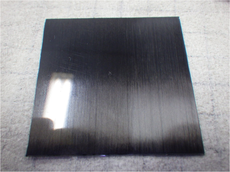
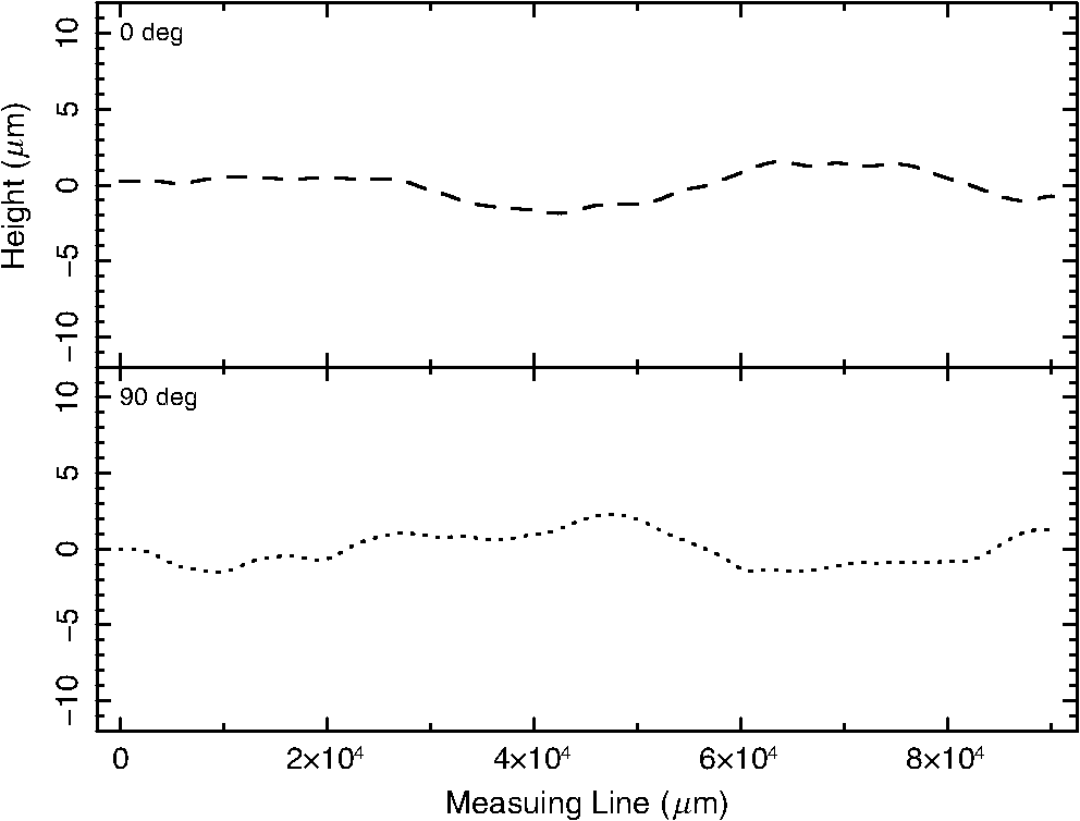
A substrate is formed by laminating prepreg sheets on the mold, which was coated with release agent or lined with release film, and curing the molded sheets with applied pressure and heat. We employ a vacuum-bagging method for applying pressure on the laminated prepreg. In the vacuum-bagging method, both the prepregs and the mold are bagged by seal film and pressed by atmospheric pressure after they were vacuum-sealed inside the bag. The laminate was cured for 3 h at 130°C in the vacuum bag. Figure 2 shows a photograph of the CFRP flat substrate. We measured the surface profiles of the flat substrate using laser microscopy measurements with OLS4000, which was developed by Olympus Co. Ltd. The surface profiles along the measured lines in Fig. 3 were scanned by the objective lens and evaluated by large-scale waviness, which was low-pass filtered with a cutoff wavelength of . The best sample of flat substrates was fabricated using the release film on the mold. The RMS values of the surface waviness of the sample at 0 and 90 deg were 1.0 and , respectively, and the peak-to-valley heights were 3.4 and , respectively (Fig. 4). The figure requirement of the waviness of the CFRP substrate is RMS of , which is estimated for successfully forming the reflection surface onto the CFRP substrate using the replication method. The RMS values of the sample achieved this figure requirement and a comparable level with the RMS of the float-glass mold. 3.Moisture Absorption3.1.Accelerated Moisture Absorption TestWe performed accelerated moisture absorption tests on the CFRP flat substrate. We manufactured a flat substrate sample for the tests using an 8-ply quasi-isotropic lamination of with a size of . The average thickness of the sample after curing was . The sample was dried in a thermal vacuum environment for 72 h at 60°C until the start of the moisture absorption test. The weight of the sample in the dried condition was 6.374 g [ in Eq. (1)]. We performed the drying-moist cycles using three different environments: 60°C and at relative humidity (RH) of 100%, 80°C and at RH of 100%, and in the laboratory environment at 18°C and at an RH of 37% on average. The sample was exposed to a moist environment in a closed container during the test. In the container, the sample was mounted above the surface of a pool of deionized water. The container was placed in an isothermal oven, then the inside of the container was conditioned to RH of 100% and constant temperature. The weight of the sample was measured by an electric scale with a minimum measuring range of 1 mg. The error of the weight measurement was , which was caused by a fluctuation of the laboratory environment and measurement drift of the scale over time. When the sample was removed from the container for the weight measurement, the sample had moisture on the surface. We wiped the moisture and waited a few minutes for the sample to cool to laboratory temperature. The moisture content of the sample is estimated using the following equation: where is the percentage of the moisture content and is the weight of the wet sample. Figure 5 shows the time profiles of the moisture content in the three environments.Fig. 5Time profiles of the moisture content of the CFRP substrate in the accelerated moisture absorption aging test. Black points represent the environment at 60°C with relative humidity (RH) of 100%, red points represent 80°C with RH of 100%, and green points represent the laboratory environment. The dashed lines are the fitting results using Fick’s law [Eq. (2)].  The diffusion of moisture in CFRP follows Fick’s law. For the moisture content with respect to time, the model is expressed by where is the diffusivity of CFRP, is the thickness of CFRP and is the saturated moisture content.15 The dashed lines in Fig. 5 are fitting results using Eq. (2). The time profiles of the moisture content in the three environments are well fitted by Eq. (2). Table 2 shows the parameters of the fitting results. In the flat substrate at 60°C with RH of 100%, the moisture content was saturated at 50 h and gained 1.5%. At 80°C with RH of 100%, the moisture content was saturated at 30 h and gained 1.5%. In the laboratory environment, the moisture content was stabilized at 0.4% after 400 h. The times required to reach the saturated moisture content of the laboratory environment (0.41%) at 60°C with RH of 100% and 80°C with RH of 100% were 2.2 and 1.4 h, respectively. Therefore, the acceleration rates of 60 and 80°C at RH of 100% compared to that of the laboratory environment were estimated to be and 290 times, respectively.Table 2Fick’s law fitting parameters of the time profile of the moisture content in the three environments.
Note: RH, relative humidity. Experimentally, the temperature dependency of the diffusivity may obey the Arrhenius equation, which is expressed as , where and are the constants of each material and is the absolute temperature. From our results of the diffusivities at 60 and 80°C, the of the substrate was calculated as 2616. This value is lower than the value of 5000 to 6500 obtained in a previous report.16 3.2.Effect of Moisture Absorption for the CFRP SubstrateWe also measured the deformation of the sample after drying and moisture absorption. The sample was continuously exposed to repeated drying and moisture absorption. We measured the surface waviness of the 90 deg measuring line using the same procedure as described in Sec. 2. The black line in Fig. 6 is the surface waviness of the sample in the laboratory environment before drying. The red line in Fig. 6 is the surface waviness after drying at 60°C from the laboratory environment. The RMS of the red line was , which was worse than that of the black line (). The green line in Fig. 6 is the surface waviness after the moisture absorption reached the saturated moisture content at 60°C with RH of 100% from the dried condition. The RMS of the green line was , which was smaller than that of the red line, but did not reach that of the black line. The blue line in Fig. 6 is the surface waviness after drying at 60°C from the moist condition. The blue line had a geometry similar to the red line, but the RMS of the blue line was , which was slightly worse than that of the red line. We estimated that this the effect was due to the moisture absorption cycle from the waviness for mirror application. The slope error of the differential waviness between the cycle start and end is calculated to be 2.4 arc min. The deformation due to the moisture absorption cycle is a serious effect for a subarc-minute x-ray telescope. The results also suggest that the history of drying and moisture absorption would influence the deformation of CFRP. In practice, the CFRP mirror in an x-ray telescope will experience moisture absorption due to the humid air during storage on the ground and will be dried after it moves to a space environment. Thus, moisture absorption due to humid air on the ground should be minimized to reduce deformation of the CFRP substrate on-board. Fig. 6Measurement results of the surface waviness of the flat substrate sample in the moist-drying cycle which were measured by the laser microscope with a cutoff wavelength of at the center-line parallel to 90 deg. The solid black line shows the surface waviness in the laboratory environment before drying. The dashed red line shows the surface waviness after drying at 60°C from the solid black line. The dash-dot green line shows the surface waviness after moisture absorption to reach the saturated moisture content at 60°C with RH of 100% from the dashed red line. The dotted blue line is the surface waviness after drying at 60°C from the dash-dot green line.  3.3.Co-Curing Thin Sheets on CFRPTo reduce the speed of moisture absorption of CFRP, we manufactured CFRP substrates with thin sheets, which had the function of moisture prevention. We first applied Super-Invar foil with a thickness of as the moisture prevention sheet, which had a lower thermal expansion coefficient than other metals. The foil was simultaneously co-cured with the prepreg laminate using essentially the same procedure as that of the sample for the accelerated moisture absorption test in Sec. 3.1, but the release film was replaced with the co-curing foil. The foil was bonded to the laminate by the resin in the prepregs. The surfaces on the co-cured sample showed no cracks or rips in the foil. We note that the foil was not covered on the side surface of the laminate with a thickness of ; the foil only covered the top and bottom surface of size . We performed an accelerated moisture absorption test of the co-cured sample with Super-Invar foil (hereafter called the Super-Invar sample) at 60°C with RH of 100%. Figure 7 shows the time profile of the moisture content. In the co-cured sample, we calculate the moisture content using where and are the same as that described in Eq. (1), and is the weight of the co-cured foil. Table 3 shows the fitting results of the time profile of the moisture content of the Super-Invar sample with Eq. (2). In the fitting, the moisture content was fixed to the value fitted with the un-co-cured sample of 1.50%, assuming the moisture content of the Super-Invar sample would reach the same level as the un-co-cured sample after a sufficient duration. We define the rate of moisture absorption (), which is derived from the diffusivity as where is the time of the half-saturated moisture content of and , is the weight gain at given by and is the surface area of the sample. The rate of absorption of the Super-Invar sample was , which was 440 times lower than that of the un-co-cured sample of ; however, this absorption rate was not zero because the Super-Invar foil did not cover the side of the sample surface. The co-curing with Super-Invar foil was successful for reducing the moisture absorption rate of the CFRP flat substrate. However, the metal foil may be difficult to smoothly fit to curved surfaces, such as the Wolter-I designed substrate.Fig. 7Time profiles of the thermal moisture at a temperature of 60°C with RH of 100%. Black points represent the un-co-cured sample, red points represent the sample co-cured with Super-Invar foil, green points represent the sample co-cured with IB-PET-PXB film, and blue points represent the sample co-cured with SiOx COP film. Dashed lines are the results of the profiles fitted with Fick’s law [Eq. (2)], where the saturated moisture content is fixed to the value of the un-co-cured sample. Dotted lines show the fitting results in the region in which the profiles were well fitted by the Fick’s law. 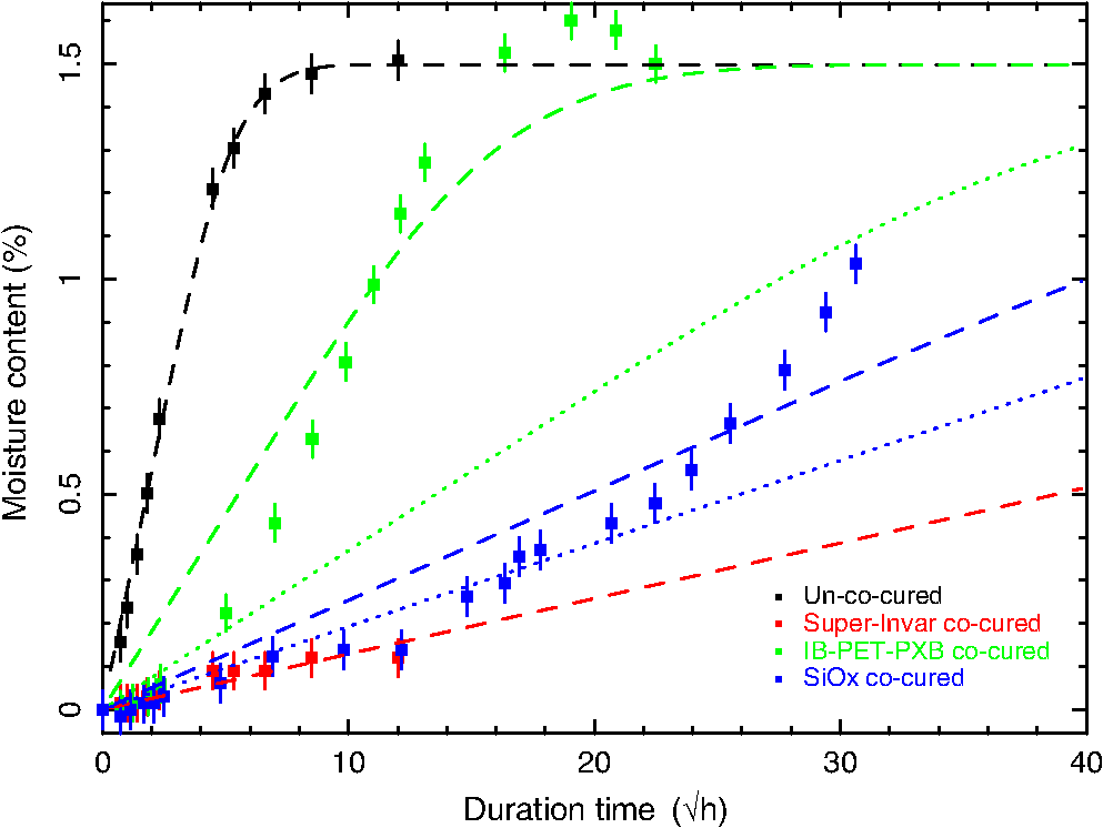 Table 3The Fick’s law fitting parameters for the time profile of the moisture content for the un-co-cured and co-cured samples at 60°C with RH of 100%.
We next attempted to co-cure functional plastic films with a low water-vapor transmissivity. The film was expected to fit the curved surface of Wolter-I designed substrate due to the flexible properties of the film. We manufactured the sample co-cured -thick polyethylene terephthalate film, which was named IB-PET-PXB and developed by Dai Nippon Printing Co. Ltd. The IB-PET-PXB film is a transparent metallized film on which alumina is deposited; IB-PET-PXB has high-barrier properties against moisture and oxygen with a water-vapor transmissivity of (Ref. 17) . Figure 7 shows the time profile of the moisture content of the IB-PET-PXB sample at 60°C with RH of 100%. Table 3 shows the fitting result of the time profile of the moisture content with Eq. (2) fixed to the value of the saturated moisture content of the un-co-cured sample (1.50%). The time profile of the IB-PET-PXB sample was not well fitted with Eq. (2). The diffusivity changed from small to large around the duration time of . The increase of the diffusivity of the IB-PET-PXB sample might be due to delamination of the deposited layer at high temperatures in humid air. We note that the temperature of 60°C for the acceleration test is higher than that of the environment for x-ray mirror use, which is typically stabilized at . To infer the diffusivity of the sample without delamination of the layer, we also performed the fitting of the profile for the duration of , where the profiles were well fitted by Eq. (2) (). The dotted lines in Fig. 7 show the fitting results for the duration time. The rate of absorption of the IB-PET-PXB sample for the considered duration time was , which was 60 times lower than that of the un-co-cured sample. We manufactured another sample co-cured with the -thick cyclic olefin polymer (COP) film, which was developed by Dai Nippon Printing Co. Ltd. The COP film is a transparent metallized film on which the SiOx layer is deposited. The water-vapor transmissivity of the SiOx COP film is , which is lower than that of the IB-PET-PXB film. Figure 7 shows the time profile of the moisture content of the SiOx COP sample at 60°C with RH of 100%. Table 3 shows the fitting parameters of the time profile of the moisture content with Eq. (2) fixed to the value of the saturated moisture content of the un-co-cured sample (1.50%). Similar to the time profile of the IB-PET-PXB sample, the time profile of the SiOx COP sample was not well fitted with Eq. (2). At first, the moisture content was similar to that of the Super-Invar sample, but the diffusivity changed from small to large in 12 to . The surface of the sample at 900 h was measured by OLS4000. Figure 8 shows the images of the SiOx COP sample surface at the start of the test and at a duration time of 900 h. The image at 900 h showed the delamination of the deposited SiOx layer. We also performed the fitting of the profile for the duration time of , where the profiles were well fitted by Eq. (2). The dotted lines in Fig. 7 show the fitting results in the duration time. The rate of absorption of the SiOx COP sample for the duration time was , which was 200 times lower than that of the un-co-cured sample. Fig. 8The images of the SiOx COP sample surface observed by OLS4000 with a objective lens. The left image was acquired at the start of the moisture absorption test at 60°C with RH of 100%, while the right image was acquired at a duration time of 900 h.  Though it would be necessary to study the effects of the deposited layer delamination in detail, co-curing of the functional thin film with low water-vapor transmissivity had the expected effect for reducing the moisture absorption rate of the CFRP substrate. Because the moisture absorption at 60°C with RH 100% is accelerated to 180 times that of the laboratory environment, the duration time of in Fig. 7 corresponds to three years () in the laboratory environment. Therefore, the moisture content of the SiOx COP sample is estimated to be of the moisture content of the un-co-cured sample after three years in a laboratory. 4.Summary and ConclusionWe have developed CFRP x-ray mirror fabrication for a telescope with a tightly nested design. The CFRP substrates are made of laminated thin prepreg sheets and formed on a mold by applying pressure and heat. In the fabrication results, the surface waviness of flat substrates ( in size) was RMS in the best products. The RMS approximately reached a level consistent with the RMS of the forming mold. We performed accelerated moisture absorption tests on the CFRP flat substrate. The diffusivity of the substrate at 60°C with an RH of 100% was calculated to be , which was times higher than that of the laboratory environment. Moreover, we also had successful results co-curing the thin sheets to reduce the speed of moisture absorption by functional sheets with low water-vapor transmissivity. Co-curing with three thin sheets of Super-Invar foil, IB-PET-PXB film, and SiOx COP film showed a reduced rate of moisture absorption that was 440, 60, and 200 times lower than that of the un-co-cured sample. We note that the IB-PET-PXB sample and the SiOx COP sample showed delamination of the deposited layer on the film at 60°C with a relative humidity of 100%, although the delamination would not occur in a typical space environment which is stabilized at . From the above results of the moisture absorption tests, the moisture content of the co-cured SiOx COP sample is estimated to be of the moisture content of the un-co-cured sample after three years in a laboratory. We showed the application of the film co-curing for moisture prevention to CFRP. We will apply the co-curing to the Wolter-I designed substrate for a future work. AcknowledgmentsThe authors are grateful to M. Sugawara for support in the fabrication and the measurement of the carbon fiber reinforced plastic substrate, and Dai Nippon Printing Co. Ltd. (DNP) for providing support for the films. The x-ray measurement was performed at BL20B2 in SPring-8 with the approval of the Japan Synchrotron Radiation Research Institute (JASRI) (Proposal No. 2012B1085, 2013A1483, 2013B1423, and 2014B1191). This work was financially supported by the JST-SENTAN (Development of Advanced Measurement and Analysis Systems) Program, the Japan Science and Technology Agency (JST). ReferencesL. V. Speybroeck,
“Einstein Observatory (HEAO-B) mirror design and performance,”
Proc. SPIE, 184 219
(1979). http://dx.doi.org/10.1117/12.957428 PSISDG 0277-786X Google Scholar
B. Aschenbach,
“Design, construction, and performance of the ROSAT high-resolution x-ray mirror assembly,”
Appl. Opt., 27 1404
(1988). http://dx.doi.org/10.1364/AO.27.001404 APOPAI 0003-6935 Google Scholar
M. C. Weisskopf et al.,
“An overview of the performance and scientific results from the Chandra X-Ray Observatory,”
Publ. Astron. Soc. Pac., 114 1
(2002). http://dx.doi.org/10.1086/338108 Google Scholar
P. J. Serlemitsos et al.,
“The x-ray telescope on board ASCA,”
Publ. Astron. Soc. Jpn., 47
(1), 105
–114
(1995). Google Scholar
P. J. Serlemitsos et al.,
“The x-ray telescope onboard Suzaku,”
Publ. Astron. Soc. Jpn., 59
(SP1), 9
–21
(2007). http://dx.doi.org/10.1093/pasj/59.sp1.S9 Google Scholar
T. Takahashi et al.,
“The ASTRO-H x-ray observatory,”
Proc. SPIE, 8443 84431Z
(2012). http://dx.doi.org/10.1117/12.926190 PSISDG 0277-786X Google Scholar
H. Awaki et al.,
“The hard x-ray telescopes to be onboard ASTRO-H,”
Appl. Opt., 53 7664
–7676
(2014). http://dx.doi.org/10.1364/AO.53.007664 APOPAI 0003-6935 Google Scholar
S. Utsunomiya, T. Kamiya and R. Shimizu,
“Development of CFRP mirrors for low-temperature application of satellite telescopes,”
Proc. SPIE, 8450 84502R
(2012). http://dx.doi.org/10.1117/12.926133 PSISDG 0277-786X Google Scholar
R. Börret, H. Glatzel and M. Shmidt,
“Manufacturing technologies for high throughput imaging x-ray telescopes: XMM CFRP technology compared to the x-ray systems,”
Proc. SPIE, 2210 348
–359
(1994). http://dx.doi.org/10.1117/12.188095 PSISDG 0277-786X Google Scholar
S. Sugita et al.,
“Studies of lightweight x-ray telescope with CFRP,”
Proc. SPIE, 9144 914447
(2014). http://dx.doi.org/10.1117/12.2054837 PSISDG 0277-786X Google Scholar
T. Iwase et al.,
“Development of the next generation x-ray telescope using CFRP as a substrate,”
in Suzaku-MAXI 2014: Expanding the Frontiers of the X-ray Universe,
160
(2014). Google Scholar
H. Salmen et al.,
“Development and production of lightweight CFRP carriers for the XMM telescope x-ray mirrors,”
Proc. SPIE, 2011 128
–137
(1994). http://dx.doi.org/10.1117/12.167192 PSISDG 0277-786X Google Scholar
M. Iye and J. Wg,
“Concept study of Japan Extremely Large Telescope,”
Proc. SPIE, 5489 417
–428
(2004). http://dx.doi.org/10.1117/12.552290 PSISDG 0277-786X Google Scholar
Y. Arao et al.,
“Out-of-plane deformation due to the ply angle misalignment in CFRP laminates (the effect of the stacking sequence on thermal deformation),”
Trans. Jpn. Soc. Mech. Eng. Ser. A, 77
(776), 619
–628
(2011). http://dx.doi.org/10.1299/kikaia.77.619 Google Scholar
J. Trigo,
“Dimensional stability characterisation of carbon fiber with epoxy and cyanate ester resin laminates due to moisture absorption,”
in Spacecraft Structures, Materials and Mechanical Engineering,
371
–376
(1996). Google Scholar
A. C. Loos and G. S. Springer,
“Moisture absorption of graphite-epoxy composite immersed in liquids and in humid air,”
J. Compos. Mater., 13 131
–147
(1979). http://dx.doi.org/10.1177/002199837901300205 Google Scholar
Dai Nippon Printing Co. Ltd., “IB type films,”
(2008) http://packaging.jp/modules/product/item-44-3.html ,” ( January ). 2008). Google Scholar
Biography |