
|
|
1.IntroductionAs a part of the development of a lightweight, high-throughput telescope with sub-arc minute angular resolution, we studied mirrors based on a thin carbon-fiber-reinforced plastic (CFRP) substrate with the original monolithic Wolter-I geometry. The composite CFRP material consists of carbon fibers and resin. Recently, space applications have been developed using CFRP as a structural element of satellites and as the body of space telescopes.1 The coefficient of elasticity of CFRP is seven times that of aluminum, while the coefficient of thermal expansion (CTE) is two orders lower than that of aluminum. Moreover, the forming flexibility of CFRP is suitable for forming original monolithic Wolter-I substrates. Therefore, CFRPs are suitable materials for thin, high-precision x-ray mirrors. An x-ray telescope designed around the CFRP substrates would have lighter weight and higher resolution than one with an aluminum substrate using the same mirror design. We have developed a monolithic x-ray mirror, using a Wolter-I type design with the CFRP substrate that is intended for use in a nested-type hard x-ray telescope (HXT). The x-ray reflector on the CFRP substrate was fabricated using the replication method that was previously adopted for the telescopes on-board Suzaku2 and ASTRO-H.3 In a previous study of x-ray mirrors on CFRP substrates, the test models for the X-ray Multi-Mirror Mission (XMM) were developed by CFRP mirrors on a parallel with electroformed Ni replicated mirrors in an early phase. The half-power diameter (HPD) of the CFRP mirror was 16 arc sec at 1.5 keV and 27 arc sec at 8 keV.4 The CFRP mirrors for the XMM mission were constructed on full-shell substrates produced by a filament-winding method, whereas we have developed our mirrors on quadrant-shell substrates by a hand lay-up method using pre-preg. The quadrant-shell substrates have a larger potential for imaging errors than the full-shell substrates because of a lower forming precision caused by lay-up uncertainty and because of the additional steps necessary for mirror assembly. On the other hand, the quadrant-shell approach has lower fabrication costs than the full-shell substrates and is applicable to the fabrication methods employed for the Suzaku/ASTRO-H telescope. One of the known disadvantages of using CFRP as a substrate for x-ray mirrors is a long-term deformation caused by swelling during aging. The swelling phenomenon is caused by moisture absorption into the resin, which is an organic compound, and influences the physical and chemical properties of the CFRP. We have developed cocuring functional sheets with low water vapor transmissivity on the CFRP substrate. Cocuring the sheets successfully reduced the moisture absorption compared to substrates that had not been cocured.5 Another disadvantage of CFRP is the microscale deformation on the substrate surface that is called print-through, and it is caused by the difference of thermal shrinkage between the carbon fiber and the resin during the curing process. In a previous study of a CFRP mirror for the XMM mission, print-through occurred in the dry state of the CFRP mirror, causing surface deformation in the surface wavelength region of . The long-term resolution of the CFRP mirrors was limited by the print-through.6 Consequently, the XMM-Newton mirrors were fabricated by electroforming, a process that is not affected by print-through but results in much more massive mirrors. In this paper, we report the current status of x-ray mirror fabrication on CFRP substrates, and the attempt to reduce the amplitude of the print-through of CFRP by curing at room temperature. X-ray measurement of the CFRP mirrors was performed during December 2014 in the BL20B2 beam-line at SPring-8, a synchrotron radiation facility, and we also report the results of the x-ray measurement of the CFRP mirrors for x-ray telescopes. 2.Effects of Print-Through, and the X-ray Reflectivity of the Carbon-Fiber-Reinforced Plastic Mirror2.1.Fabrication and Surface MeasurementIn order to study the effects of print-through on the surface of the CFRP mirror, we fabricated the replicated mirrors on CFRP flat substrates. We utilized a pre-preg sheet as the CFRP substrate material. The pre-preg sheet, which was thick, consisted of high-elasticity-type pitch fiber with epoxy resin and was developed by Nippon Graphite Fiber (model No. E7026B-05S). The CFRP flat substrate, which was and thick, was fabricated by a vacuum-bagging method that involved applying pressure and heat. The details of the CFRP substrate fabrication have been published previously.5 The surface asperity due to print-through of the CFRP flat substrate was measured by surface profiling and had a root-mean-square (RMS) roughness of . The surface roughness of the CFRP substrate itself is larger than the acceptable roughness for an x-ray reflector in the sub-nm range. We adopted a replication method to form the reflecting surface on the substrate.7 First, the metal layers, which would become the actual x-ray reflector, were sputtered onto a float-glass mold with a super-smooth surface. The CFRP substrate was glued to the metal-coated mold with epoxy in a vacuum chamber. The reflector on the float-glass was a Pt/C multilayer that was designed for hard x-ray reflection. After curing the epoxy and carefully separating from the mold, the metal surface with super-smoothing was replicated on the substrate. The details of the replication are based on the methods used previously for the mirrors in the HXT on-board ASTRO-H.8 During the replication, the epoxy between the reflection layer and the CFRP fills in the surface asperities by print-through. However, the surface asperity problem reappears again after the replication because of changes in temperature during curing. To study the effect of the print-through in the replication process, we manufactured two mirrors, which differed only in curing temperature; one (sample A) was cured at 50°C, and the other (sample B) was cured at room temperature ( on average). We measured the three-dimensional (3-D) surface profile of the mirrors using a scanning white light interferometer (Zygo NewView7300 developed by Canon). Figures 1 and 2 show the surface profiles of samples A and B across measuring regions of and . In the region, the surface profile of sample A shows the print-through structure caused by carbon fibers, and the RMS error of the surface profile is 4.2 nm. In sample B, the print-through structure is significantly smaller than that of sample A, and the RMS error of the profile is only 0.8 nm. In the region, the surface profile of sample A shows a print-through structure due to filament yarns with an RMS error of 29.8 nm. In the case of sample B, the print-through structure is again smaller than that of sample A, and the RMS error of the surface profile is 6.1 nm. Hence, the print-through on the replicated surface was significantly reduced by employing the room temperature curing. Fig. 1The 3-D profiles of the mirror surfaces in a region measured by a Zygo NewView7300 interferometer. (a) The sample cured at 50°C and (b) the sample cured at .  Fig. 2The 3-D profiles of the mirror surfaces in a region measured by a Zygo NewView7300 interferometer. (a) The sample cured at 50°C and (b) the sample cured at .  The predicted amplitude of the print-through can be estimated using the CTE of the resin contained within the CFRP. The CTE of the resin within the CFRP substrate is . The print-through by filament yarns is caused by nonuniformity of the distribution of carbon fiber in the pre-preg; the nonuniformity of resin in the thick pre-preg (E7026B-05S) had a maximum value of . The difference in curing temperature between sample A and the laboratory environment was . From these parameters, the predicted amplitude of the print-through can be estimated to be , which is roughly consistent with the height of the print-through observed experimentally on sample B. We next measured the x-ray reflectivity of the CFRP flat mirrors at the x-ray beam-line in Nagoya University. Figure 3 shows the reflectivity curve of the flat x-ray mirror determined by incident-angle scanning at 8 keV. We estimated the roughness of the reflector by fitting the reflectivity curve to a Pt/C multilayer Debye–Waller model, which has three free parameters: , the thickness of the multilayer with respect to the design value; , the thickness of the Pt (heavy element) layer with respect to the C (light element) layer; and the roughness of the surface boundary between the layers. The design values of the reflector were for the thickness of the Pt/C multilayer, 40 for the number of bilayers in the multilayer stack, and 0.4 for . From the model fitting, the roughness was calculated to be 0.5 nm. This roughness is roughly consistent with that of the ASTRO-H/HXT mirror, which consisted of a Pt/C multilayer reflector on an aluminum substrate. 2.2.Long-Term Stability of the Mirror Surface on Carbon-Fiber-Reinforced Plastic SubstrateCFRP is subject to swelling as it ages. The swelling phenomenon is caused by moisture absorption into the resin and influences the physical and chemical properties of CFRP. We evaluated the long-term stability of the mirror surface on the CFRP flat substrate by measuring its x-ray reflectivity at 8 keV. The procedure for the measurement and evaluation of the x-ray reflectivity was the same as that described in Sec. 2.1. The mirror was stored at 20°C at a relative humidity of 30% for 6 months and we measured the reflectivity of the mirror every 2 weeks. Figure 4 shows the reflectivity curves at 2-week intervals and Fig. 5 shows the time variation of the three fitting parameters (, , and roughness) with the Pt/C multilayer Debye–Waller model. These results show that the reflectivity and the fitting parameters did not exhibit any systematic degradation within an RMS deviation of 5% over 6 months. We also measured the reflectivity of a mirror that was stored for 6 months at 25°C at a relative humidity of 90%. The reflectivity and the fitting parameters in that humid environment did not show any systematic degradation either, throughout the 6-month test period. Fig. 4Reflectivity curves, measured by the grazing-angle-of-incidence method, for a mirror that was stored at 20°C and a relative humidity of 30% for 6 months; the measurements were taken at 2-week intervals. The numbers embedded in the upper graph represent the date of each measurement in yymmdd format. The term “Ratio” is the ratio between the amplitude of each point on a reflectivity curve and the corresponding point on the first curve that was recorded at the start of the measurement on April 20, 2014 (i.e., the black curve in the upper figure).  Fig. 5Fitting parameters of the reflectivity curves of Fig. 4. is the ratio of thickness between the Pt (heavy element) layer and the C (light element) layer. The -factor is the ratio of the measured thickness of the multilayer stack to the design value. The roughness is the surface roughness of the boundary between the layers. 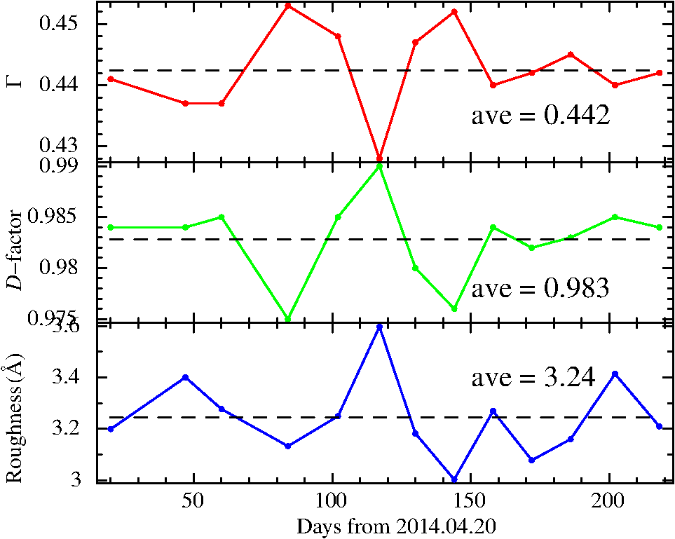 3.X-ray Measurements of X-ray Telescope Mirror3.1.Fabrication of an X-ray Mirror with Wolter-I OpticsWe fabricated quadrant-shell mirrors for the x-ray measurements. The design parameters of the mirrors are shown in Table 1. The procedure for the CFRP substrate fabrication was basically same as that for the flat substrate described in Sec. 2. The mold for the substrate was made of aluminum and designed in the shape of Wolter-I optics. Figure 6 shows a schematic view of the quadrant substrate. We fabricated two substrates (mirror A and mirror B) for the measurement, which differed from each other in the lamination construction and the thickness of the pre-preg. The constructions and the thicknesses are shown in Table 2. The shapes of the center generatrix line (Fig. 6) of the CFRP substrates were measured by an NH-6 laser profiler (MITAKA Kohki Co. Ltd.). The RMS values of the residuals between the data for the center generatrix line and the design value of the mirrors are presented in Table 2. Table 1Design parameters of the CFRP mirror.
Fig. 6Schematic view of a quadrant substrate and the measuring line, determined by the NH-6 laser profiler.  Table 2Parameters of the mirrors for x-ray measurement.
The procedure of replication is also basically the same as that of the flat panel that was described in Sec. 2. We attempted the replication using a glass tube developed by Schott, for which the RMS errors of surface profile in the generatrix lines were 0.5 to . The reflector of the mirrors was a single Pt layer with a thickness of , and the thickness of the epoxy was . The substrate was cured on the mold at room temperature for a week in an effort to reduce the effect of the print-through. The above replication procedure was performed individually for the two stages of the substrate (paraboloid and hyperboloid). Figure 7 shows the shapes of the center generatrix line of the mirrors measured by the NH-6. The RMS values of the residual between the data for the center generatrix line and the design value of the mirror are shown in Table 2. The mirrors were attached to the housing using top and bottom alignment bars, which had grooves to hold the edges of the mirrors. The alignment of the mirrors was performed to optimize the performance of each mirror, and not necessarily that of the complete telescope. Fig. 7The shapes of the center generatrix lines measured by the NH-6. (a) The data for mirror A and (b) for mirror B. The red lines are measurement data of the mirrors, the black dotted lines are design values of the mold, and the blue lines are the residuals between the data and the design value. The region in the position of was not replicated.  3.2.X-Ray Measurement at BL20B2 in SPring-8We performed x-ray measurements of the CFRP mirrors for the x-ray telescope at BL20B2 in SPring-8, which is a third-generation synchrotron radiation facility located in Hyogo, Japan. The acceleration energy of the electron beam is 8 GeV. The beam-line 20B2 employs a bending-magnet as a light source and is allocated to medical applications and various imaging techniques in the energy range of 5 to 113 keV. The total length of this beam-line is 215 m from the light source.9 The setup for the x-ray measurement is a legacy system, based on equipment originally constructed for ASTRO-H/HXT,3 SUMIT, and .10 The mirrors were illuminated with a collimated x-ray beam, and a reflection spot image was obtained by a detector located downstream. Figure 8 shows a schematic view of the measurement of a focused image with a spot beam. The x-ray imaging detector consists of a scintillator in front of a CCD with a pixel size of . Figure 9 shows the setup of the mirrors in the housing at the BL20B2. Fig. 8The schematic view of the measurement setup used to produce a focused image with a spot beam, copied from Ogasaka et al.10 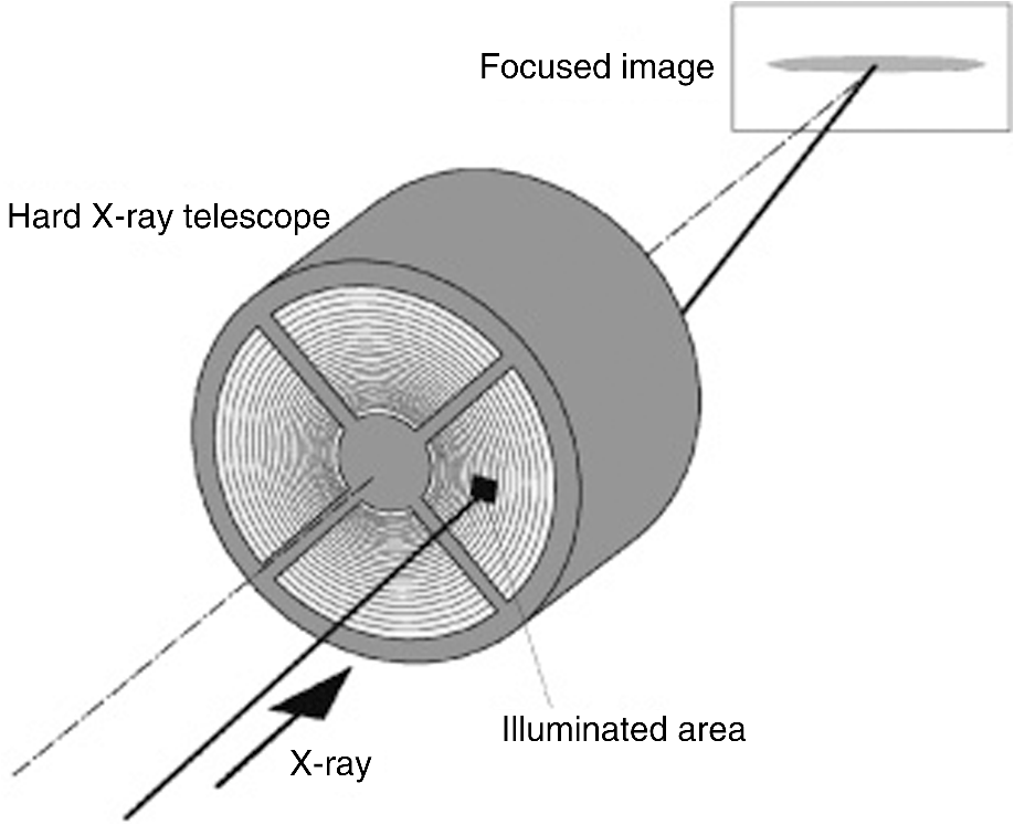 Fig. 9The setup of the 200-mm diameter mirrors in the housing, viewed from the bottom side at BL20B2. The collimated x-ray beam enters the mirrors from the back side in this picture.  The x-ray beam was monochromatized to 20 keV by a Si(311) double-crystal monochromator and collimated using an upstream slit (TC1 slit1). We obtained the local spot images of the x-ray beam over the mirrors in a 2.86-deg pitch () by rotating the housing in the circumferential direction. The slit size was 10 mm in the horizontal direction and 1 mm in the vertical direction, which corresponds to the direction of the mirrors, and covered the entire area of the reflecting surface of the mirrors in the radial direction. The distance between the mirrors and the detector during the scanning was 8406 mm. Figure 10 shows one of the spot images, obtained with a slit size of . The unsymmetrical shape of the image arises from defocusing in the circumferential direction caused by the fact that the distance between the housing and the detector is shorter than the focal length of the mirrors. Figure 11 shows the projection of the spot image onto the Dy axis, which is equal to the radial axis of the mirror. We evaluated the point spread of the spot images based on their HPD. Figure 12 shows the HPDs of the spot images with a slit size of obtained by the circumferential rotation scan, and Table 3 shows the statistics of the HPD of the spot images in each mirror. The typical error of HPD value was , which was estimated by the previous measurements. As shown in Fig. 12, the HPDs at 10 deg from the circumferential edges of the mirrors are considerably larger than those in the central region of the mirrors. By comparing the HPD of the spot images and the surface profile of the center generatrix line (RMS values presented in Table 2), it can be seen that the surface profile of mirror B was smaller than that of mirror A, but the HPDs of the spot images were larger. As shown in Fig. 7, the shape of mirror B has a small-scale deformation with a periodicity of . This small deformation may cause the dispersion of the image through the two reflections of the x-ray beam. Fig. 10The spot image of the collimated beam produced by the CFRP mirror with a slit size of (Dy and Dz, respectively) at the scan angle of 125.3 deg. The units of the Dy and Dz axes have been converted from CCD pixels to arc min. The defect in the spot image is the shadow of the alignment bar. 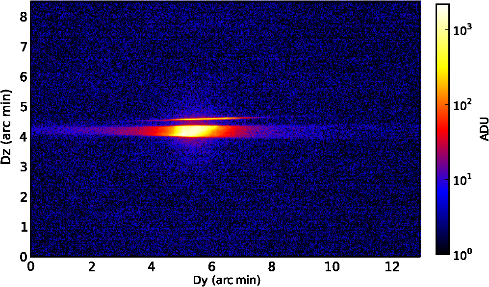 Fig. 11The projection of the spot image of Fig. 10 on the Dy axis. The green line is an encircled energy function from the peak of the spot image. The HPD was calculated to be 0.61 arc min.  Table 3Statistics of the HPDs (arc min) of the spot images with a slit size of 10×1 mm obtained by a circumferential rotation scan.
We subsequently obtained the spot images of a part of the mirrors using a slit size of . For this measurement, the distance between the mirrors and the detector was 12,000 mm. Figure 13 shows the spot image obtained with a slit size of at a scan angle of 123.6 deg, and Fig. 14 shows the projection of the spot image onto the Dy axis. The HPD of the spot image was 0.38 arc min. The HPD of the spot image in the case of slit size (0.61 arc min) was larger than that of the case (0.38 arc min) for the same scan angle. In the measurement, the image blurring could be caused by defocusing due to the short distance between the mirror and the detector. The effect of the defocusing is estimated to be , where is the height of the mirror, is the incident angle of the mirror, is the distance between the mirror and the detector, and is the focal length of the mirror. From the configuration of the mirror, the effect of the defocusing at the distance of 8406 mm was estimated to cause a point spread of 0.1 mm on the detector. This can be converted to 0.04 arc min, which is insufficient to explain the discrepancy of the HPD between the slit sizes of and . In Fig. 10, the peak position of the image in the Dy direction changes along the Dz direction. In sliced profiles along the Dz direction, the peak positions of the profile at a Dz of 4 (arc min) differed from the peak position at a Dz of 4.5 (arc min) by . This is roughly consistent with the blurring of the image in comparison with that of the case. The difference between the sliced images along the Dz direction implies that the angle between the two stages of the mirror was slightly misaligned. Possible reasons for the misalignment include deformation due to misalignment of the alignment bars, imperfection of the shape of the CFRP substrate in the circumferential direction, and nonuniformity of the epoxy thickness in the replication. We need to study each of these elements to achieve improvement of the imaging performance. Fig. 13The spot image of the collimated beam produced by the CFRP mirror with a slit size of (Dy and Dz, respectively) and a scan angle of 123.6 deg. The units of the Dy and Dz axes have been converted from CCD pixels to arc min.  Fig. 14The projection of the spot image of Fig. 13 onto the Dy axis. The green line is an encircled energy function from the peak of the spot image. The HPD was calculated to be 0.38 arc min.  4.Summary and ConclusionWe have developed a fabrication method for x-ray mirrors using CFRP for an x-ray telescope with a tightly nested design. The CFRP substrates are made of laminated thin pre-preg sheets and are formed on a mold by applying pressure and heat. We employed a replication method to fabricate the mirror surface on the CFRP substrate. The method employed procedures based on those of the mirror for the HXT on-board ASTRO-H. We studied the effect of print-through on the surface of the replicated CFRP flat mirror after replication, and we successfully obtained a smooth surface with an RMS error of 0.8 nm in the surface profile over a region after room temperature curing. The reflectivity was measured using x-rays at 8 keV and the roughness of the mirror was calculated to be 0.5 nm from the model fitting; this is comparable to that of the ASTRO-H/HXT mirror. We also measured the long-term stability of the mirror surface by measuring its x-ray reflectivity over a period of 6 months; the reflectivity and the fitting parameters showed no degradation. In the replicated mirror designed for x-ray telescopes, we fabricated quadrant-shell mirrors with a diameter of 200 mm, and we performed x-ray measurements of the mirrors at BL20B2 in the SPring-8 synchrotron radiation facility. We obtained the reflection images of the mirrors using an x-ray spot beam at 20 keV with a slit size of in the radial and circumferential directions, respectively. The averaged HPDs of the images in one of the mirrors were 1.2 arc min in the circumferential center of the mirror and 3.0 arc min at the circumferential end of the mirror. In the case of spot images with a smaller slit size of , we achieved the HPD of 0.38 arc min in the best case. We have demonstrated a successful application of CFRP for an x-ray mirror using room temperature curing to reduce the print-through, and we have confirmed the long-term stability of the mirror surface. In the x-ray measurement of the CFRP mirror for x-ray telescope, a part of the spot images of the mirrors achieved the requirement for sub-arc min resolution. Our future goals are to achieve sub-arc min HPDs over the mirrors by improving the shape of the mirror in the circumferential edge regions and using higher precision CFRP substrates whose RMS error are less than . In addition, we will attempt to attach the mirrors to the telescope housing in the next x-ray measurement for precision alignment of the mirrors. AcknowledgmentsThe authors were grateful to M. Sugawara for support in the fabrication and the measurement of the CFRP substrate. The x-ray measurement was performed at BL20B2 in SPring-8 with the approval of the Japan Synchrotron Radiation Research Institute (JASRI) (Proposal No. 2012B1085, 2013A1483, 2013B1423, and 2014B1191). This work was financially supported by the JST-SENTAN (Development of Advanced Measurement and Analysis Systems) Program, the Japan Science and Technology Agency (JST), and JSPS KAKENHI Grant Nos. 15H02070 (H.A.) and 15K13464 (H.M.). ReferencesS. Utsunomiya, T. Kamiya and R. Shimizu,
“Development of CFRP mirrors for low-temperature application of satellite telescopes,”
Proc. SPIE, 8450 84502R
(2012). http://dx.doi.org/10.1117/12.926133 PSISDG 0277-786X Google Scholar
P. J. Serlemitsos and Y. Soong,
“Foil x-ray mirrors,”
Astrophys. Space Sci., 239 177
–196
(1996). http://dx.doi.org/10.1007/BF00645773 APSSBE 0004-640X Google Scholar
H. Awaki et al.,
“The hard x-ray telescopes to be onboard ASTRO-H,”
Appl. Opt., 53 7664
–7676
(2014). http://dx.doi.org/10.1364/AO.53.007664 APOPAI 0003-6935 Google Scholar
D. Pauscbinger et al.,
“Production of thin-walled lightweight CFRP/EPOXY x-ray mirrors for the XMM telescope,”
Proc. SPIE, 1742 235
–244
(1992). http://dx.doi.org/10.1117/12.140557 PSISDG 0277-786X Google Scholar
S. Sugita et al.,
“Studies of the moisture absorption of thin carbon-fiber-reinforced plastic substrates for x-ray mirrors,”
J. Astron. Telesc. Instrum. Syst., 2
(3), 034003
(2015). http://dx.doi.org/10.1117/1.JATIS.1.3.034003 Google Scholar
R. Börret, H. Glatzel and M. Shmidt,
“Manufacturing technologies for high throughput imaging x-ray telescopes: XMM CFRP technology compared to the x-ray systems,”
Proc. SPIE, 2210 348
–359
(1994). http://dx.doi.org/10.1117/12.188095 PSISDG 0277-786X Google Scholar
P. J. Serlemitsos et al.,
“The x-ray telescope on board ASCA,”
Publ. Astron. Soc. Jpn., 47
(1), 105
–114
(1995). PASJAC 0004-6264 Google Scholar
A. Furuzawa et al.,
“The current status of ASTRO-H/HXT development facility,”
Proc. SPIE, 7437 743709
(2009). http://dx.doi.org/10.1117/12.825771 PSISDG 0277-786X Google Scholar
S. Goto et al.,
“Construction and commissioning of a 215-m-long beamline at SPring-8,”
Nucl. Instrum. Methods A, 467 682
–685
(2001). http://dx.doi.org/10.1016/S0168-9002(01)00445-4 Google Scholar
Y. Ogasaka et al.,
“Characterization of a hard x-ray telescope at synchrotron facility SPring-8,”
Jpn. J. Appl. Phys., 47 5743
–5754
(2008). http://dx.doi.org/10.1143/JJAP.47.5743 Google Scholar
Biography |
|||||||||||||||||||||||||||||||||||||


