
|
|
1.IntroductionThe Astrophysics Focused Telescope Assets (AFTA) coronagraph1 is designed for direct imaging of nearby exoplanet systems in reflected starlight. Exoplanets ranging in size from Earth-like to Jovian, when imaged in reflected starlight at visible wavelengths, will be fainter than their parent stars by factors of to . Taking advantage of the stability of the space environment, an actively corrected coronagraph is capable of extreme high-contrast imaging at small angular separations from the star. The AFTA coronagraph is designed for raw imaging contrast of or better within angular separations of a few from the star, with the expectation that postprocessing of image data will extend detection sensitivities an order of magnitude fainter (). The AFTA coronagraph will directly image (for the first time) exoplanet populations in reflected starlight at visible wavelengths, while enabling spectroscopic characterizations of exoplanets and faint circumstellar debris and dust structures. The hybrid Lyot coronagraph (HLC) forms a full 360-deg high-contrast dark field where faint exoplanets and orbiting dust/debris disks can be separated from the overwhelming glare of the central star. The high-contrast dark field of view is characterized as a low background of coherent speckles scattered from the central star into the surrounding field. We show that inner working angles (IWA) of 3 (142 marcsec for the 2.4-m AFTA telescope at 550 nm wavelength) and somewhat smaller are feasible with the HLC and that its performance is robust and stable. This development combines model predictions and laboratory validations, as previously demonstrated for Terrestrial Planet Finder-Coronagraph Milestones #1 and #2,2,3 [which demonstrated monochromatic and 10% broadband starlight suppression in the high-contrast imaging testbed (HCIT) at the Jet Propulsion Laboratory (JPL)], in more recent demonstrations carried out by the ACCESS concept study4 under the Astrophysics Strategic Mission Concept Studies (ASMCS) program, and the hybrid Lyot technology demonstrations5,6 under the Technology Development for Exoplanet Mission (SAT-TDEM) program. These earlier coronagraph designs anticipated a dedicated space observatory with an off-axis unobscured primary mirror. The AFTA coronagraph changes the paradigm somewhat, most importantly due to the predefined 2.4-m pupil diameter and pupil obscurations of the secondary mirror and its hexapod support struts. The AFTA coronagraph speaks directly to the objectives of the Astro2010 New Worlds New Horizons decadal recommendation for New Worlds Technology Development.7 2.Hybrid Lyot Coronagraph Design ObjectivesThe AFTA coronagraph is designed for the detection and spectroscopic characterization of mature exoplanets and exoplanet systems in reflected starlight. The design trades are tailored to desired performance metrics and the optical characteristics of the Wide Field InfraRed Survey Telescope-Astrophysics Focused Telescope Assets (WFIRST-AFTA) telescope. Contrast is the ratio between the peak brightness of the central star and the mean brightness of the field of background stellar speckles averaged over a specified area in the coronagraph field of view. Raw contrast refers to the native contrast in the coronagraph images prior to any postprocessing. The inner and outer working angles (IWA and OWA) are the inner and outer radii of the high-contrast dark field cleared by the coronagraph. These are defined in terms of the central wavelength and the diameter of the entrance pupil of the telescope. Spectral bandwidth is the ratio , where is the full width at half maximum transmittance of the band-defining optical filter and is the central wavelength. The ratio is conserved end-to-end through the optical system. Our optical propagation models, based on the Fresnel approximation, incorporate the optical characteristics of the Lyot coronagraph elements, mirror surfaces, the deformable mirrors (DMs), and the CCD imager. Extensive prior laboratory experiments with unobscured apertures and a variety of linear Lyot coronagraphs4–6 have validated our coronagraph performance models down to contrast levels of , IWAs of 3 , and bandwidths to 20%, thereby establishing that our predictive models are thoroughly understood. The detection of exoplanets requires the disambiguation of the exoplanet signal from the background field of stellar speckles, which is made increasingly difficult at small angular separations due to at least three factors: (1) background speckles are increasingly unpredictable due to sensitivity to low-order wavefront errors induced by telescope and instrument jitter and drift, (2) the roll-angle diversity available to sample the background speckle field is severely reduced at smaller radii,8 and (3) small sample statistics at small working angles impose a penalty in confidence levels for exoplanet detection.9 We return to these considerations in Sec. 4. We seek a balance between desired but competing qualities of raw image contrast, IWA, spectral bandwidth, overall throughput, and sharpness of the exoplanet point-spread functions (PSFs). Our design objectives are as follows: (1) Raw image contrast better than at visible (450 to 950 nm) wavelengths, as needed to image an exoplanet in reflected starlight, requiring wavefront stability that is uniquely available to a space observatory. Such contrast levels are beyond the reach of large ground-based telescopes, which are expected to achieve contrasts of in the coming decade.10,11 (2) Tolerance to telescope pointing jitter and finite stellar diameters, both in the range of a few milliarcseconds, while preserving high-contrast performance. (3) Spectral bandwidth of 10% or greater, as will be required to capture scarce photons. (4) IWA or closer to the star to capture and disambiguate significant numbers of exoplanets. (5) Coronagraph efficiency, defined in terms of throughput losses introduced by the coronagraph elements, to be better than 40%, again to capture scarce photons. (6) Minimum instrument complexity, using a minimum number of critical elements and alignments, leading to a system with accurate optical models and reliable performance predictions. In practical terms, complexity affects our ability to successfully fabricate, align, and ultimately develop accurate models for science performance. Confidence limits for exoplanet detections will depend on detailed characteristics of the coronagraph PSFs, telescope stability, and practical methods of postprocessing of data. 3.Hybrid Lyot Coronagraph Design ElementsHLC is one of the two observing modes for the AFTA coronagraph instrument (CGI), which accommodates both the HLC and the shaped pupil coronagraph on a common optical bench, with modes that are selectable by exchanging a number of critical optical elements.12 For clarity, we sketch the coronagraph optical system in Fig. 1 showing just the essential components of the HLC. HLC is a hybrid of the classical occulting coronagraph and the phase mask coronagraph, with active control of wavefront phase and amplitude. Moving from left to right in Fig. 1, a pair of DMs conditions the optical wavefront that reaches the focal plane mask. These DMs perform high-order amplitude and phase manipulations that clear a high-contrast dark field in the coronagraph focal plane, correct for low-order optical imperfections and alignment drifts in the AFTA telescope, and help suppress the diffraction from the six AFTA secondary support struts. With an intensity transmittance of about , the metal-dielectric focal plane mask immediately rejects most of the starlight, removing it from the coronagraph system while directing the reflected starlight to the low-order wavefront sensor (LOWFS).13 The remaining fraction of the star’s PSF passes through and around the occulting mask. A thickness-profiled dielectric layer superimposed on the base metallic layer of the focal plane mask shapes the phase of the light transmitted by the focal plane mask, such that coherent remnants of the starlight interfere to further darken the high-contrast dark field. The Lyot stop masks the starlight diffracted from the struts and pupil boundaries of the AFTA telescope, completing the prior work of the DMs. Wavelength-dependent diffraction from the focal plane mask, followed by the spatial filtering effects of the Lyot mask, introduces a measure of chromaticity that assists in extending high contrast to a larger spectral bandwidth. Fig. 1Sketch of the essential elements of the actively corrected hybrid Lyot coronagraph (HLC). Coronagraph elements are highlighted in green, and wavefront control elements in yellow. Diagram unfolds the optical system and depicts powered elements as lenses. The AFTA telescope pupil is obscured by the secondary mirror and its six support struts. The coronagraph includes just two elements, a focal plane mask and a Lyot pupil stop. Amplitude and phase of the optical wavefront are probed and manipulated with a sequential pair of deformable mirrors to form the high-contrast coronagraph dark field of view. The first deformable mirror (DM) is located near the system pupil, providing the most direct control of large phase errors in the telescope. The second DM, downstream of the pupil and working in concert with the first, provides the most direct control of induced amplitude errors via the Talbot effect. Arrow pointing to the low-order wavefront sensor indicates that the starlight reflected from the tilted focal plane element is used for feedback to the pointing control and low-order wavefront correction systems. 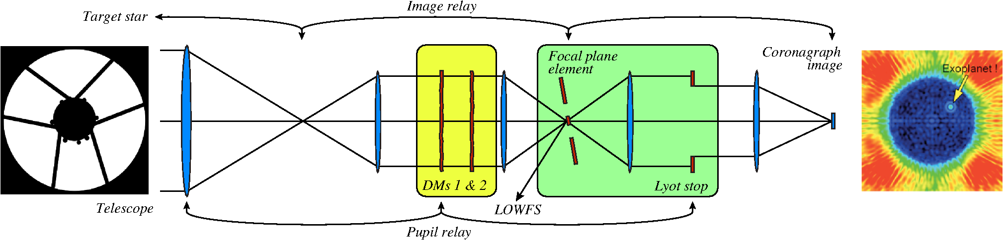 Our current, and still evolving, HLC design utilizes the WFIRST-AFTA engineering model predictions, itself a work in progress, including the telescope with 2.4-m primary mirror obscured by its central secondary mirror and support struts. By design, the IWA is 3 . Spectral bandwidth centered at is computed as the performance averaged over nine wavelengths spanning the 10% band. Engineering analysis of the AFTA telescope provides preliminary estimates of the primary and secondary mirror surface figures, line-of-sight telescope pointing jitter, and low-order wavefront errors due to thermal-mechanical drift in the telescope structures in the baseline L2 orbit. As diagramed in Fig. 2, the design process starts with an initial design, such as the band-limited Lyot configuration,14 then generates physically realizable design adjustments against criteria that balance spectral bandwidth, contrast, IWA, tolerance for pointing jitter, and overall throughput. The procedure is iterative, with small linear steps in the free parameters, by the method of gradient descent, with parameter regularization to guide the convergence toward a desired balance of design objectives. A number of design parameters are fixed at the outset and held constant to simplify the optimizations. These fixed trial parameters, which include the radius and circular shape of the focal plane mask (and target IWA), dimensions of the Lyot stop, and spectral bandwidth are selected on the basis of prior experience and can be revised in subsequent optimization runs. The procedure includes as free parameters the thickness profiles of the focal plane mask (composed of one nickel and one dielectric layer) and the surface figure settings on each of the two actuator DMs. Standard multilayer thin film interference code (which generates layer thickness profiles to match specified attenuation and phase profiles) is combined with wavefront control code (which finds the optimal deformable mirror settings) in an end-to-end optical propagation model. DM settings are optimized in stages by spatial filtering, progressing from large low-order corrections in the early iterations to small high-order control in the later stages. Fig. 2Block diagram of the design optimization process. An optimization algorithm is embedded in a computational loop that computes and evaluates the coronagraph performance metrics. The instantaneous state of the coronagraph elements is conveyed by a (a) set of static trial parameters plus (b) the free parameters for the HLC focal plane mask and DM settings. The iterative process starts with the initial trial design and iteratively adjusts the focal plane mask and DM settings to improve the performance, as scored against a weighted set of performance objectives.  Our optical propagation model, based on the Fresnel approximation, incorporates the physical characteristics of the Lyot coronagraph elements, mirror surfaces, the DMs, and the pixel dimensions of the CCD imager. The code is written in Python and has been cross-checked with the publicly distributed PROPER code15 for this work and for prior design studies,4 typically showing agreement to within computer rounding errors. Since the underlying physics is not in question, the accuracy of our model predictions is limited only by the fidelity of our physical descriptions of the critical coronagraph elements. This model has consistently predicted laboratory contrast performance within 15% in prior demonstrations in the HCIT. The effects of stellar diameter and pointing jitter are idealized in our model as the convolution of a uniform disk for the star (neglecting limb darkening) and a Gaussian-weighted distribution of tip/tilt pointing offsets. The representative target star is given an angular diameter of 1 mas (roughly equal to the angular diameter of the sun at 10 pc). Pointing jitter up to a few milliarcseconds is also incorporated into the process. The presence of these two angular offset distributions is represented in our model as a cluster of incoherent point sources with the specified distribution of angular offsets in the sky. The quoted coronagraph contrast is the weighted average of contrasts computed for a large number of representative angular offsets. As shown in Fig. 3, the focal plane Lyot mask is composed of two thin film layers, one metallic and the other of dielectric material, superimposed on a glass substrate. The metal layer is dominant in defining the attenuation profile. Nickel is selected for its stable and repeatable optical characteristics. A thickness-profiled dielectric layer provides an additional degree of freedom to control the wavefront phase as well, with the selection of the dielectric material based on the manufacturing method. For manufacturing simplicity, the focal plane mask is constrained to be circular with a uniform intensity transmittance of about . Future design work will exploit the additional degrees of freedom available with other radially and azimuthally profiled optical densities. Fig. 3The hybrid Lyot focal plane mask provides control of both the real and imaginary parts of the telescope point spread function. The metal and dielectric layer thickness profiles, sized for and an beam, are illustrated here, plotted as a radial profile and as imaged by an atomic force microscope at JPL’s Micro Devices Laboratory. The mask is formed on the first surface of a thin antireflection-coated glass substrate. Starlight is incident from the top as oriented in the figure. 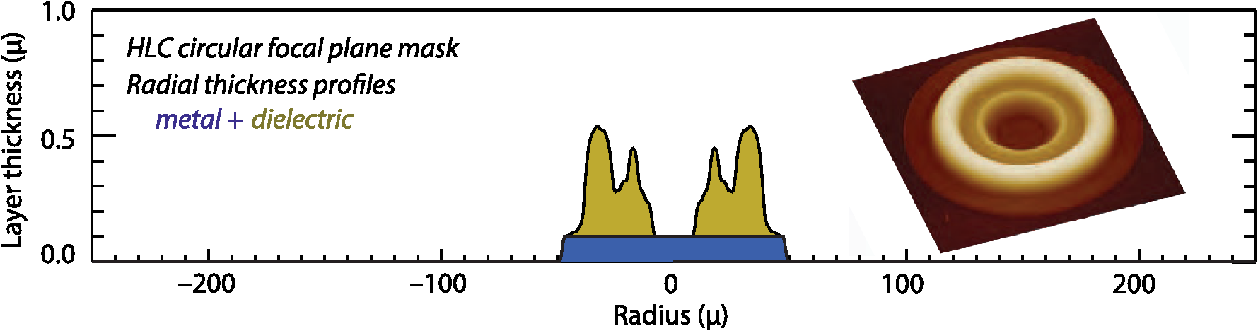 The tilted focal plane mask reflects about 60% of the incident starlight, which is captured by LOWFS camera13 to provide both a bias-free guide signal for pointing jitter stabilization and a monitor of low-order wavefront drifts. The guide signal is used by a fast steering mirror internal to the coronagraph to reduce the pointing jitter inherent to the AFTA telescope system. A thickness dimple of diameter 1.22 is designed into the center of the dielectric pattern to phase-shift about half the reflected starlight by radians, as required for the Zernike method of low-order wavefront sensing. Two fabrication methods for the HLC focal plane masks have been developed and demonstrated in our JPL laboratories: (1) a vacuum evaporation approach with nickel and (or cryolite) layers on a fused silica substrate and (2) a lithography approach developed at JPL’s Micro Devices Laboratory using e-beam-sensitive polymethylglutarimide (PMGI) resist as the dielectric. Masks designed and fabricated for current testbed experiments are sized for in an beam. The dimensions of masks for other central wavelengths are scaled by wavelength with only minor changes to the design profiles. The vacuum deposition method relies on the direct electron beam evaporation of thickness-profiled metal and dielectric thin films onto a fused silica glass substrate. Both films are formed in a single vacuum deposition run. The deposition patterns are defined by a stencil mask fabricated on a silicon-oxide-silicon wafer, which is placed between the deposition source and the glass substrate. The stencil and substrate are separated by , creating a predictable and repeatable apodization of the circular edge. The shape of the nickel layer is defined by a diameter aperture in the stencil mask. A thickness-profiled layer of dielectric material is deposited on top of the metal, this time using a diameter aperture which is rastered in circular patterns with a piezo-actuated stage to form the specified radial profile. Again, the separation between stencil and substrate create a repeatable apodization, which is accounted for in the mask design. The dielectric material can be either or cryolite, materials that have nearly the same indices of refraction, hence are optically equivalent for our application. All materials are stable and robust for flight in a radiation environment. The lithography approach occurs in two steps. First, the nickel layer is vacuum deposited on a fused silica substrate as a sharp-edged circular disk using a lift-off photolithography resist pattern. A uniform PMGI dielectric layer is then spun on over the nickel feature, and e-beam exposure is used to develop the specified thickness profile. For simplicity and compatibility of the two fabrication methods, the current HLC focal plane mask is designed with a uniformly thick metal layer, making the nickel layer compatible with both processes.16 The pupil plane Lyot stop, shown in Fig. 4, was fixed for this design effort and will be the subject of future refinements. It is fabricated, either by wire discharge machining or chemical etching, as a transmitting mask pattern cut into a free-standing thin metallic foil. Fig. 4The Lyot mask is defined and held constant for these optimizations. The AFTA pupil, as projected to the coronagraph, is shown in black, the Lyot stop in blue, and the pattern of transmitted light is white. Future work will explore other possible Lyot configurations.  Wavefront control is carried out with a pair of DMs in series in a shared collimated beam. These two DMs control the complex (amplitude and phase) wavefront upstream before the coronagraph elements. The DMs each have a array of lead magnesium niobate (PMN) electrostrictive ceramic actuators on a 1-mm pitch, driving a continuous fused-silica mirror face sheet. This pair of DMs, separated by 1 m in a collimated beam, provides leverage over both the real and imaginary parts of the propagating wavefront. The ability to control both amplitude and phase in a propagating wavefront is easily visualized as the Talbot effect,17 and has been utilized to explicitly suppress diffraction from pupil obscurations.18 The DMs are used in concert with the focal plane and Lyot plane masks to generate the high-contrast dark field, as well as to correct for static optical design and manufacturing imperfections and to compensate for slow thermal drift in the telescope optics. Wavefront control with the DMs is modeled in terms of measured influence profiles as illustrated in Fig. 5. The shape of the DM mirror surface is predicted as a sum of surface figure influence profiles, common to all actuators, scaled to peak surface heights calibrated individually for each actuator. Linearity applies for small surface deformations, such that the overall surface shape of the DM can be computed as the simple sum of individual influence profiles. An illustration of the technique is shown in Fig. 5, where an subarray of actuators has been actuated to equal height. The result, as expected, is a simple displacement of the flat mirror surface (with roll-off effects at the edges) rising to 1.4 times the height of a single isolated actuator poke. The flat top predicted by this superposition model is uniform in height to 0.4% rms, which serves as an indication of the fidelity of this simple model. This method has proven adequate for past testbed demonstrations. Anticipating that AFTA will need still better DM characterizations, in support of more rapid convergence of the iterative DM control algorithms and high fidelity open-loop control of low-order wavefront drift, the accuracy of the DM model will be improved and extensive calibrations will be carried out. The AFTA coronagraph DMs are manufactured by Northrop Grumman Xinetics, extending a technology that has been in development and continuous use in HCIT vacuum coronagraph demonstrations for over 10 years.19 The DMs are robust for launch, having been successfully tested to well over 12 Gs rms in three-axis vibration tests. We call for a highly reliable DM driver system and electrical interconnects, and a minimum of weak actuators. We have developed strategies for the mitigation of small numbers of disconnected or weak actuators, as has been demonstrated in the course of high-contrast coronagraph demonstrations with prototype DMs on our HCIT testbeds. The AFTA program is developing a full flight qualification plan for these DMs in the coming year. Fig. 5Wavefront control is modeled in terms of a pair of actuator DMs: (a) The surface figure influence function for individual actuators, arrayed across the DM with a 1-mm pitch, is measured in our vacuum surface gauge on a 0.1-mm sample grid, hence 100 sample pixels per actuator. (b) The effect of the DM on wavefront phase is modeled by the additive superposition of these influence functions. An illustration of this linear superposition, where an subarray of DM actuators has been modeled with equal displacements, results in the expected table top that is uniform in height to within 0.4% rms. (c) The AFTA coronagraph DMs, manufactured by Northrop Grumman Xinetics, provide an active area measuring .  4.Hybrid Lyot Coronagraph Science PerformanceThe HLC creates a 360-deg high-contrast dark field, with IWA and OWA of 3 and 10 respectively, and a spectral bandwidth centered at , as shown in Fig. 6. We rely on the DMs to correct for static wavefront errors in the telescope and instrument optics. The curves are for the raw contrast prior to image processing. The contrast predictions in the figure include estimated static mirror surface errors in the AFTA telescope and four representative levels of residual pointing jitter. The dark field extends, with rapidly degrading contrast and throughput, inward to 2.5 . Bright speckles outside of the 10 OWA are masked with a circular field stop at a focal plane downstream of the coronagraph elements, to eliminate possible CCD blooming and leakage into the dark field. Model simulations have shown that the expected levels of static wavefront errors introduced by the AFTA telescope optics, typical small coronagraph elements, and the as-fabricated focal plane masks are easily corrected by the DMs and have only negligible effects on the predicted coronagraph performance. Fig. 6The HLC high-contrast dark field, centered at 550-nm wavelength with a 10% bandwidth, extends in radius from 3 to 10 : (a) The azimuthally averaged raw contrast for four representative levels of residual pointing jitter. (b) The HLC provides 360-deg high-contrast dark field, shown here for 0.4-mas residual jitter and a 1-mas diameter star.  Pointing jitter is the subject of extensive engineering analysis and has been incorporated into our instrument models and design. By design, the HLC is relatively insensitive to tip/tilt jitter. Of greater concern are longer-term wavefront drifts due to thermal gradients in the telescope structures. Figure 7 illustrates the sensitivity of the HLC to low-order drift, where we have perturbed the static AFTA-HLC wavefront (10% bandwidth, 1-mas diameter star, 0.4-mas rms pointing jitter) in the form of the ten Zernike terms from tip/tilt to spherical aberration. Thermal drift in the telescope generates dominantly low-order variations in the wavefront.20 Uncertainties in these aberrations and the resulting azimuthal variances increase sharply at smaller working angles, as shown in Fig. 8. The low-order terms generate annular ring-like patterns, with azimuthal “noise” that is sensitive to small wavefront irregularities. These are difficult to model accurately due to the stack-up of uncertainties in the low-order errors. Fig. 7Coronagraph point spread functions showing the patterns of wavefront error sensitivities in the form of low-order Zernike terms, representative of errors introduced by drifts in telescope alignment and thermal gradients across the primary mirror. At far left, the HLC high-contrast dark field with nominal static errors, 10% bandwidth, 0.4-mas rms pointing jitter, and 1-mas stellar diameter. Then, shown left to right, the coronagraph PSFs with the addition of 100-pm rms wavefront error at the telescope primary mirror in the forms of tip, tilt, defocus, astigmatism, coma, trefoil, or spherical aberration. 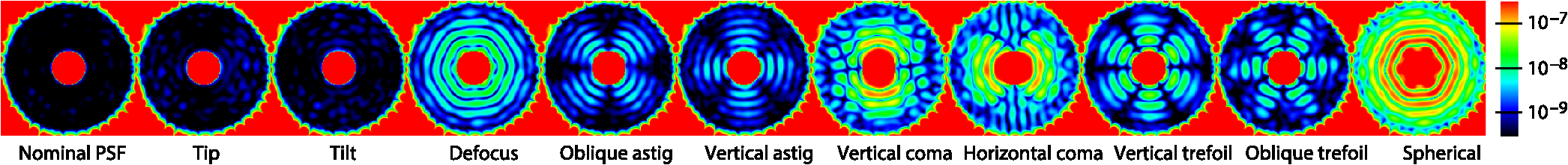 Fig. 8These plots indicate the azimuthal “noise” in background speckle intensities over a range of radial separations from the star that is introduced by adding 100-pm rms of the respective Zernike wavefront errors to the AFTA primary mirror. At each radial separation, the plot shows the rms azimuthal variations between the static PSF and the perturbed PSFs.  The AFTA observatory will routinely perform rolls up to about the line of sight. Thermal drifts in the telescope optical system and the evolution of speckles in the coronagraph dark field will be monitored and mitigated by the low-order wavefront sensing and control (LOWFS&C) system13 to be acceptably small over the times needed to collect the images. It is the objective of the LOWFS&C to reduce the collective effects of low-order wavefront drift to well below 100 pm rms. The science performance of the HLC is illustrated in Fig. 9, which overplots the expected brightnesses relative to the star for a selection of known radial velocity (RV) exoplanets and the predicted raw contrast curves for the current HLC design. Four curves [Fig. 9(a)] show the azimuthally averaged raw contrast in the presence of residual pointing jitters of 0.2, 0.4, 0.8, and 1.6-mas rms, respectively, spanning the estimated range from best to worst after pointing correction by the tip/tilt fast steering mirror internal to the coronagraph. The raw contrast curves include the nominal static wavefront errors of the AFTA telescope. Fig. 9(a) The raw image contrast for the AFTA-HLC, using HLC design as last updated in June 2014 with a 3.0 inner working angle (IWA) and a 10% spectral bandwidth centered on , a stellar diameter of 1 mas, and various levels of rms residual pointing jitter as indicated. The raw contrast curves are overplotted on fiducial marks for the known RV planets in reflected starlight with angular separations of 100 mas or more. (b) Contrast estimate following a modest level of postprocessing, using angular differential imaging for a reduction of the contrast floor and a 95% completeness criterion ( sigma above background speckle noise) for positive planet detections above the AFTA detection threshold. The HLC supports detection of the known RV planets at angular separations between 2.8 and 10 (132 to 475 mas) for both the nominal (0.4-mas rms) and worst case (1.6-mas rms) residual jitter levels. Plot symbols for the brighter stars are progressively larger and redder than the fainter stars. 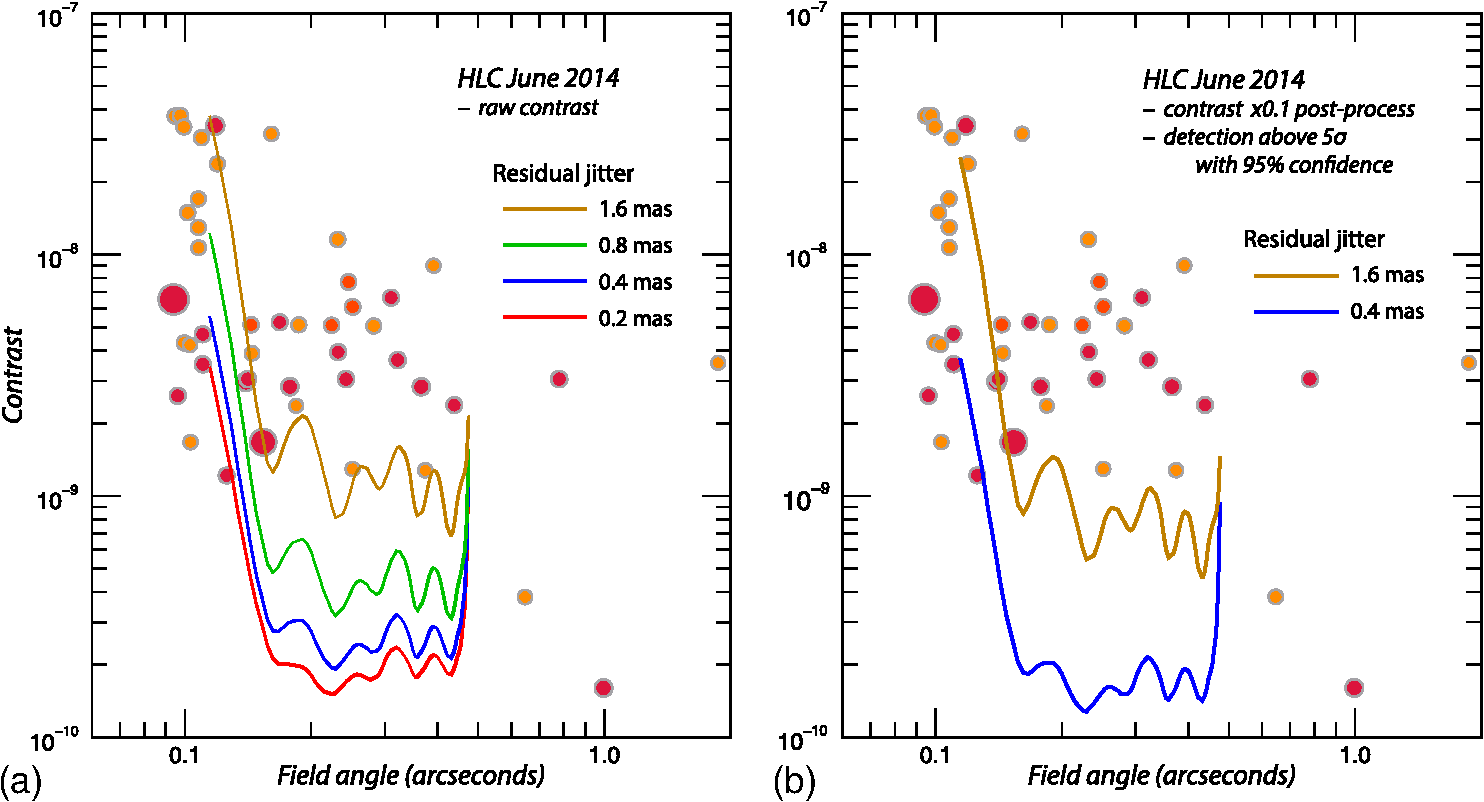 For a representative sample of accessible exoplanets, we selected the 45 RV planets from the Extrasolar Planets Encylopaedia21 that lists semimajor axis/star distances greater than 0.1 mas. We assume circular orbits and Lambertian scattering from the atmosphere at 70-deg phase and 550-nm wavelength.22 Among these 45 stars, 36 have stellar diameters less than 1 mas, 4 have diameters between 1 and 2 mas, 1 has a diameter of 2.6 mas, 3 are K giants larger than 2.6 mas, and we have eliminated 1 eclipsing binary from the list. Our assumed 1-mas star diameter is conservative for the majority of these stars. For reference, the combined effects of pointing jitter (0 to 1.6 mas rms) and stellar diameter (0 to 10 mas) are listed in Table 1, on the understanding that jitter and stellar diameter will shift the HLC contrast curves vertically relative to the baseline case by the tabulated delta contrast values. The column in bold font highlights the delta contrast for a 1-mas star. For example, star diameters less than 1.0-mas shift the HLC contrast curves upward by no more than compared to zero diameter, while stars up to 2.5-mas shift the contrast curves upward by no more than . Given the small number of stellar diameters in this list greater than 1 mas, we simply note that contrast performance will be degraded for larger angular diameters as indicated in Table 1. Table 1Effect of pointing jitter and stellar diameter on hybrid Lyot coronagraph contrast. This lists delta contrast values (×10−9) averaged over the full 3 to 10 λ0/D dark field corresponding to various amounts of pointing jitter (mas rms) and stellar diameter (mas). The column in bold font, for 1.0-mas stellar diameter, corresponds to the model results described in Sec. 3 and the data shown in Figs. 6–9.
Various strategies for disambiguating exoplanets from underlying quasi-static stellar speckles are under study. A simple and robust method relies on back-to-back sequences of images over various telescope roll-angles followed by postprocessing of the data. Techniques based on roll-angle diversity place the fewest demands on telescope stability and have been applied with great success to both ground-based and HST images. Angular differential imaging (ADI) yields information about the background speckle field at given radii from the star,8 but with AFTA roll-angles limited to , angular separations of 3 or more from the star are required to displace the background speckle field by just 1.5 , as needed to disambiguate exoplanets from background speckles. The paucity of background reference speckles at small working angles leads to the regime of small sample statistics, with a corresponding penalty in statistical confidence limits for exoplanet detections.9,23 Setting a criterion of 95% confidence for exoplanet detection above the detection threshold leads to a detection threshold above the rms background speckle noise. We equate rms speckle background with the mean speckle intensities, a property of speckle statistics. Assuming that ADI can improve background contrast by a factor of 10, then giving back a factor of 6.7 in contrast leads to the postprocessing detection threshold curves in Fig. 9(b). Further analysis, based on better estimates of telescope stability, LOWFS&C corrections, pointing performance, and postprocessing yields, will enable more refined detection estimates and opportunities to refine the coronagraph performance for maximum science yields. The figure indicates that the AFTA-HLC can detect essentially all of the known RV exoplanets orbiting at angular separations greater than about 2.8 (132 mas), given sufficient integration time, even in the case of the worst expected jitter control. From the current AFTA CGI science yield estimates,24 it is evident that the brightest 15 of these RV exoplanets can all be detected with a total integration time of 3 days. We anticipate that there are yet unseen exoplanet systems that will be revealed in ongoing RV searches from the ground and in discovery-mode observations with the AFTA coronagraph. To harvest more of the known RV planets, one would adjust the HLC design trades in favor of smaller IWAs, subject to the severe penalties of small sample statistics and sensitivities of instrument contrast to uncorrected low-order wavefront jitter and drifts. Design adjustments for smaller IWAs may prove practical, and will be considered, as the optical stabilities of the AFTA systems become better known. 5.ConclusionsWe have extended previous work with the hybrid metal-dielectric Lyot coronagraph design, this time for the WFIRST-AFTA telescope. The preliminary design shown here indicates that while the AFTA pupil obscurations tend to reduce overall coronagraph performance in comparison with the unobscured telescope, the HLC nevertheless provides contrast, IWA, spectral bandwidth, and overall throughput at levels that enable a pioneering program of direct imaging and spectroscopy of exoplanet systems in reflected starlight at visible wavelengths. Ongoing work will further investigate and refine these designs, exploring trial parameters not far removed from the current ones, seeking better science performance and optimal tolerances to jitter and drift in the telescope optics, while accommodating the precise details of the AFTA telescope as such information becomes available. For example, a preliminary HLC design for 15% spectral bandwidth yields a dark field contrast that is modestly degraded from the above by about a factor of 2, with performance otherwise nearly identical to the 10% design. We have used our laboratory-validated design procedure based on an agile software package that encompasses mask design, wavefront sensing and control, optical tolerancing and diagnostics, and realistic physical characteristics of the coronagraph and telescope. Our experience opens a new design path for extreme high-contrast imaging with a wide variety of obscured telescopes, and we are optimistic that significant further advances will follow. The AFTA coronagraph is one of the two main approaches that are under NASA study for the direct imaging and spectroscopy of exoplanet systems. Analyses have shown that three basic coronagraph types (hybrid Lyot, shaped pupil, and PIAACMC) can be effectively tailored to the AFTA pupil geometry.20 Each of these coronagraph methods relies on precision control of pointing jitter, correction of low-order thermal drifts in the telescope optics, and high-order manipulations of the wavefront with DMs. The coronagraph instrument can be integrated with the telescope systems and optically tested as an end-to-end system prior to launch. The second major approach is the starshade,25 a large optimally shaped occulter flying in formation at large separations from a conventional space telescope. Ongoing mission concept studies will evaluate and compare potential science yields, engineering challenges, hardware maturity, and overall costs for these two main methods. These methods may ultimately be shown to provide complementary science capabilities, with an agile space coronagraph exploring numerous exoplanet systems over multiple epochs, and the starshade following up with deep exposures on selected high-priority targets. The Lyot approach provides a number of science advantages for the AFTA coronagraph. It is the one AFTA coronagraph with a full 360-deg field of view at small IWAs, ideal for initial planet searches while also providing the most complete basis for estimates of the innermost background speckle field. It provides the best raw contrast, which works to reduce the degree of postprocessing needed to separate the planet from background speckles, thereby reducing integration times and ultimately relaxing engineering requirements for long-term telescope stability. It offers the smallest sensitivity to pointing jitter among the baseline coronagraph methods. We refer to a current summary of numerical modeling of the AFTA coronagraph20 for further comparisons between the coronagraph methods. The AFTA coronagraph will secure a foothold in pioneering exoplanet science and space technology. It actualizes the National Research Council’s New Worlds New Horizons7 recommendations for technology development, leading to the direct imaging and spectroscopic characterizations of nearby exoplanet systems. Performance of the AFTA coronagraph will help illuminate the pathways for New Worlds Technology Development in preparation for next-decade exoplanet missions, providing empirical data for future design trades among science yields, telescope size, stability, pointing, wavefront control, and postprocessing techniques. AcknowledgmentsThe research described in this paper was carried out at the Jet Propulsion Laboratory, California Institute of Technology, under a contract with the National Aeronautics and Space Administration. © 2015 California Institute of Technology. ReferencesD. Spergel et al.,
“WFIRST-AFTA 2015 report by the science definition team and WFIRST study office,”
(2015) http://wfirst.gsfc.nasa.gov/science/sdt_public/WFIRST-AFTA_SDT_Report_150310_Final.pdf Google Scholar
J. Trauger et al.,
“TPF-C Milestone #1 Report,”
(2006). Google Scholar
B. Kern et al.,
“TPF-C Milestone #2 Report,”
(2008). Google Scholar
J. Trauger et al.,
“ACCESS—a concept study for the direct imaging and spectroscopy of exoplanetary systems,”
Proc. SPIE, 7731 773128
(2010). http://dx.doi.org/10.1117/12.858301 PSISDG 0277-786X Google Scholar
J. Trauger et al.,
“A hybrid Lyot coronagraph for the direct imaging and spectroscopy of exoplanet systems: recent results and prospects,”
Proc. SPIE, 8151 81510G
(2011). http://dx.doi.org/10.1117/12.895032 PSISDG 0277-786X Google Scholar
J. Trauger et al.,
“Complex apodization Lyot coronagraphy for the direct imaging of exoplanet systems: design, fabrication, and laboratory demonstration,”
Proc. SPIE, 8442 84424Q
(2012). http://dx.doi.org/10.1117/12.926663 PSISDG 0277-786X Google Scholar
National Research Council, “New worlds, new horizons in astronomy and astrophysics,”
(2010) http://www.nap.edu/catalog.php?record_id=12951 Google Scholar
C. Marois et al.,
“Angular differential imaging: a powerful high-contrast imaging technique,”
Astrophys. J., 641 556
(2006). http://dx.doi.org/10.1086/500401 ASJOAB 0004-637X Google Scholar
D. Mawet et al.,
“Fundamental limitations of high contrast imaging as small angles set by small sample statistics,”
Astrophys. J., 792 97
(2014). http://dx.doi.org/10.1088/0004-637X/792/2/97 ASJOAB 0004-637X Google Scholar
J. L. Bezuit et al.,
“SPHERE: a Planet Finder instrument for the VLT,”
Proc. SPIE, 7014 701418
(2014). http://dx.doi.org/10.1117/12.790120 PSISDG 0277-786X Google Scholar
B. Macintosh et al.,
“First light of the Gemini planet imager,”
Proc. Natl. Acad. Sci. U. S. A., 111 12661
(2014). http://dx.doi.org/10.1073/pnas.1304215111 PNCCD5 Google Scholar
M. C. Noecker et al.,
“Coronagraph instrument for WFIRST-AFTA,”
J. Astron. Telesc. Instrum. Syst.,
(2015). Google Scholar
F. Shi et al.,
“Low order wavefront sensing and control for the WFIRST-AFTA coronagraph,”
Proc. SPIE, 9605 960509
(2015). http://dx.doi.org/10.1117/12.2188775 PSISDG 0277-786X Google Scholar
M. Kuchner and W. Traub,
“A coronagraph with a band-limited mask for finding terrestrial planets,”
Astrophys. J., 570 900
(2002). http://dx.doi.org/10.1086/339625 ASJOAB 0004-637X Google Scholar
J. E. Krist,
“PROPER: an optical propagation library for IDL,”
Proc. SPIE, 6675 66750P
(2007). http://dx.doi.org/10.1117/12.731179 PSISDG 0277-786X Google Scholar
B.-S. Seo et al.,
“Hybrid Lyot coronagraph for WFIRST-AFTA: occulter fabrication and high contrast narrowband testbed demonstration,”
J. Astron. Telesc. Instrum. Syst.,
(2015). Google Scholar
J. W. Goodman, Introduction to Fourier Optics, McGraw-Hill, New York
(1988). Google Scholar
L. Pueyo and C. Norman,
“High contrast imaging with arbitrary apertures: active compensation of aperture discontinuities,”
Astrophys. J., 769 102
(2013). http://dx.doi.org/10.1088/0004-637X/769/2/102 ASJOAB 0004-637X Google Scholar
J. Trauger,
“Performance of a precision high-density deformable mirror for extremely high contrast imaging astronomy from space,”
Proc. SPIE, 4854 1
–8
(2003). http://dx.doi.org/10.1117/12.460027 PSISDG 0277-786X Google Scholar
J. Krist, B. Nemati and B. Mennesson,
“Numerical modeling of the proposed WFIRST-AFTA coronagraphs and their predicted performances,”
J. Astron. Telesc. Instrum. Syst., 2
(1), 011003
(2015). http://dx.doi.org/10.1117/1.JATIS.2.1.011003 Google Scholar
J. Schneider et al.,
“The Extrasolar Planets Encyclopaedia,”
(2015) http://exoplanet.eu Google Scholar
R. A. Brown,
“Single-visit photometric and obscurational completeness,”
Astrophys. J., 624 1010
(2005). http://dx.doi.org/10.1086/429124 ASJOAB 0004-637X Google Scholar
C. Marois et al.,
“Confidence level and sensitivity limits in high contrast imaging,”
Astrophys. J., 673 647
(2008). http://dx.doi.org/10.1086/523839 ASJOAB 0004-637X Google Scholar
W. A. Traub et al.,
“Science yield estimate with the WFIRST-ATA coronagraph,”
J. Astron. Telesc. Instrum. Syst.,
(2015). Google Scholar
S. Seager,
“The future of spectroscopic life detection on exoplanets,”
Proc. Natl. Acad. Sci. U. S. A., 111 12634
(2014). http://dx.doi.org/10.1073/pnas.1304213111 PNCCD5 Google Scholar
BiographyJohn Trauger is a senior research scientist at the Jet Propulsion Laboratory. He has developed science mission concepts and enabling optical technologies for precision optical wavefront control and high-contrast imaging of exoplanetary systems from space. He served as the principal investigator for the Wide Field and Planetary Camera 2 on the Hubble Space Telescope. Dwight Moody is a technologist at the Jet Propulsion Laboratory. He has been responsible for the development and implementation of numerical methods for the optimization of the hybrid Lyot coronagraph design and methods for wavefront analysis and control. John Krist is a research scientist at the Jet Propulsion Laboratory and the lead of the AFTA coronagraph optical modeling team. He is author of the PROPER optical propagation library and the Tiny Tim PSF modeling software for the Hubble and Spitzer space telescopes. His main interests are optical modeling, wavefront control, and observations of debris disks using the Hubble Space Telescope. |


